
Enhancement-mode hfet circuit arrangement having high power and a high threshold voltage

a technology of enhanced mode and circuit arrangement, which is applied in the direction of transistors, electronic switching, pulse techniques, etc., can solve the problems of increasing voltage levels, requiring more voltage levels, and generally not being satisfactory, and achieves high threshold voltage

Active Publication Date: 2011-12-22
POWER INTEGRATIONS INC
View PDF4 Cites 46 Cited by
  • Summary
  • Abstract
  • Description
  • Claims
  • Application Information

AI Technical Summary

Benefits of technology

[0008]In accordance with yet another aspect of the invention, a method is provided for forming an enhancement-mode HFET circuit having a high threshold voltage. The method includes providing an enhancement-mode HFET having a first threshold voltage that is less than a desired threshold voltage. A voltage shifter and a load resistive element are also provided. A first terminal of the voltage shifter and a first terminal of the load resistive element are coupled to a gate of the enhancement-mode HFET such that a second threshold voltage applied to a second terminal of the voltage shifter is equal to the desired threshold voltage.

Problems solved by technology

Such an arrangement often results in a more complicated circuit and requires more voltage levels such as negative voltages.
Unfortunately, such attempts have generally not been satisfactory when pursuing a high positive threshold voltage because of problems such as poor on-state currents, poor breakdown voltages and lower operational speeds due to the resistance and capacitance in the gate regions as well as damage that is caused to the gate regions during fabrication.

Method used


Image

  • Enhancement-mode hfet circuit arrangement having high power and a high threshold voltage
  • Enhancement-mode hfet circuit arrangement having high power and a high threshold voltage
  • Enhancement-mode hfet circuit arrangement having high power and a high threshold voltage

Examples


Embodiment Construction

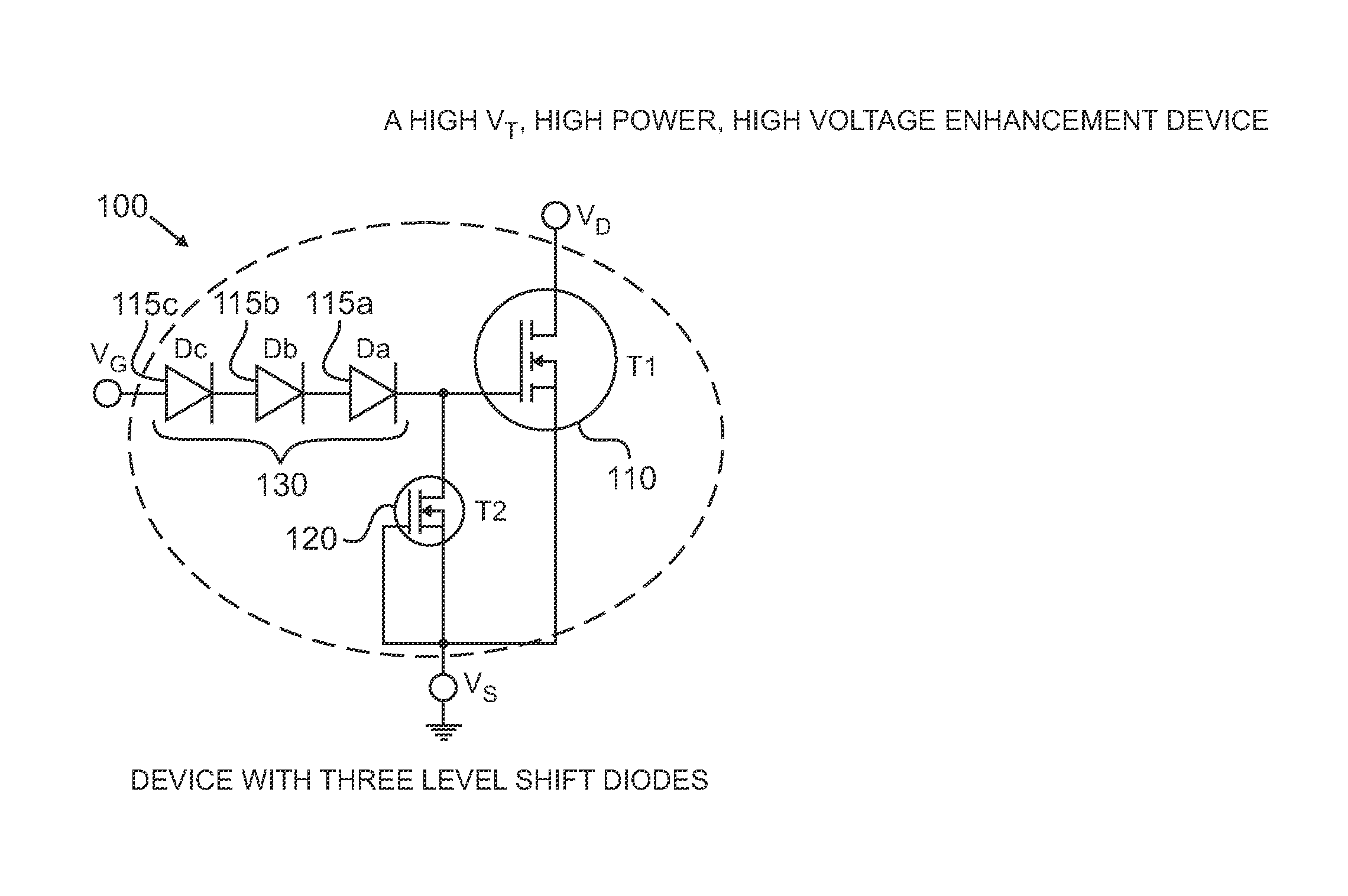
[0024]The present inventors have recognized that a GaN-based enhancement mode HFET arrangement having a high on-state current, high operating voltage, high switching speed as well as a high threshold voltage can be produced from a GaN-based enhancement mode HFET arrangement having high on-state current, high operating voltage and a low threshold voltage. As detailed below, this can be accomplished by combining such a GaN-based enhancement mode HFET with other components such as voltage shifter and a load resistor.

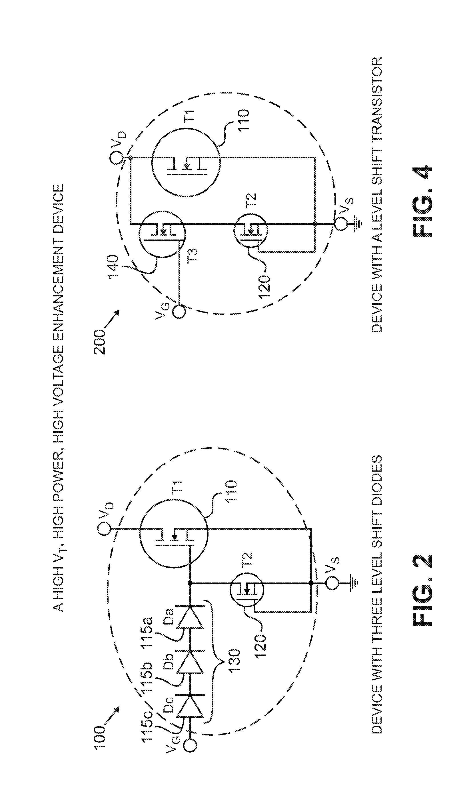
[0025]FIG. 2 shows a first example of a HFET circuit arrangement 100 constructed in accordance with the principles of the present invention. The HFET arrangement 100 includes an enhancement mode HFET 110 having the aforementioned characteristics (i.e., high on-state current, high operating voltage and a low threshold voltage, such as a threshold voltage between about 0.1V to 1.0V, for instance). Such a HFET 110 can be readily manufactured in accordance with known techniques...


PUM

PropertyMeasurementUnit
threshold voltageaaaaaaaaaa
forward voltage dropaaaaaaaaaa
threshold voltageaaaaaaaaaa

Abstract

A circuit includes input drain, source and gate nodes. The circuit also includes a group III nitride enhancement-mode HFET having a source, drain and gate and a voltage shifter having a first terminal connected to the gate of the enhancement mode HFET at a common junction. The circuit also includes a load resistive element connected to the common junction. The drain of the enhancement-mode HFET serves as the input drain node, the source of the enhancement-mode HFET serves as the input source node and a second terminal of the voltage shifter serves as the input gate node.

Description

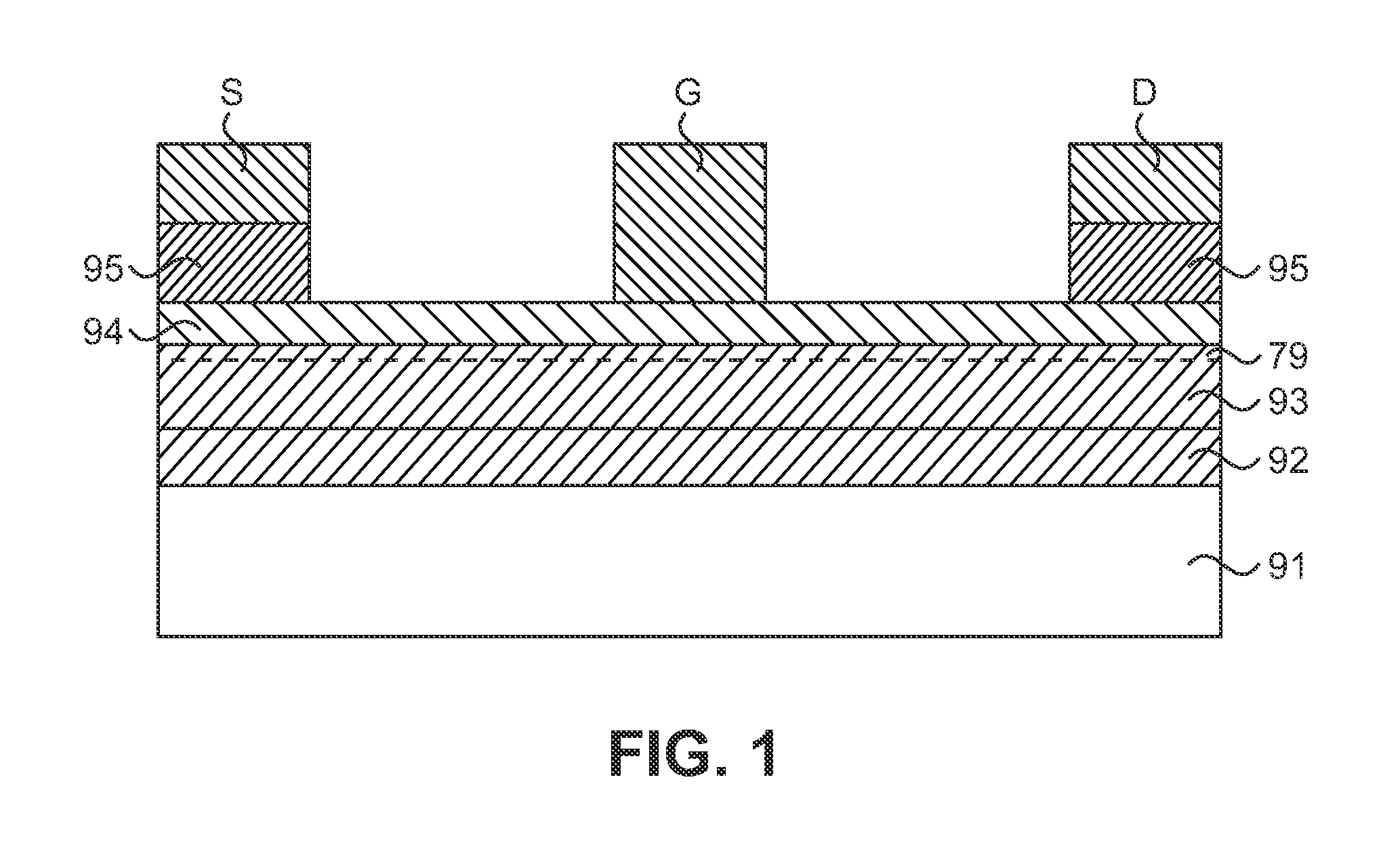
FIELD OF THE INVENTION[0001]The present invention relates generally to a Group III nitride compound semiconductor HFET such as a GaN-based HFET, and more particularly to a circuit that employs a GaN-based HFET having a low threshold voltage and which functions as a GaN-based HFET having a higher threshold voltage, a high on-state current and high speed.BACKGROUND OF THE INVENTION[0002]GaN-based Heterojunction Field Effect Transistors (HFETs) using a wide bandgap semiconductor such as GaN, AlGaN, InGaN, AlGaN, InAlN, AlInGaN and the like have received much attention as a power device for high power application since they are one order of magnitude or more smaller in on-resistance than transistors using Si or GaAs, are capable of operating at higher temperature with high current and can withstand high voltage applications.[0003]One example of a conventional GaN-based HFET is shown in FIG. 1. IN FIG. 1, as well as the figures that follow, like reference numerals are used to denote like...

Claims


Application Information

Patent Timeline
Patent Type & Authority Applications(United States)
IPC IPC(8): H01L29/737H01L29/20H01L21/335
CPCH01L27/0605H01L29/2003H01L29/402H01L29/41725H01L29/41758H01L27/0629H01L29/4236H01L29/7787H03K2017/6875H01L27/0617H01L29/42316
Inventor XIN, XIAOBINPOPHRISTIC, MILANSHUR, MICHAEL
Owner POWER INTEGRATIONS INC
Learn More