Methods of surface modification for improving electrophoretic display performance

a surface modification and electrophoretic technology, applied in the field of electrophoretic display, can solve the problems of severe narrowing of processing and formulation windows for acceptable display performance, and achieve the effects of improving surface properties, reducing electro-optic response time, and high contrast ratio

Inactive Publication Date: 2005-03-22
E INK CALIFORNIA
View PDF23 Cites 38 Cited by
  • Summary
  • Abstract
  • Description
  • Claims
  • Application Information

AI Technical Summary

Benefits of technology

The microcups which have undergone any of the treatment methods of the invention show significant improvement in their surface properties, such as chemical functionality, surface roughness, surface tension, morphology, surface charge, surface reflectivity, surface conductivity and optical properties, particularly optical density in the visible light region. As a result, an electrophoretic display formed from the treated microcups has many advantages. For example, the display shows a higher contrast ratio, lower electro-optic response time, lower driving voltage, longer shelf life, higher image bistability and higher threshold voltage. In addition, it exhibits an improved image quality by reducing undesirable scum formation or irreversible particle deposition on the microcup surface. The surface modification also considerably improves the coating and / or adhesion quality in the filling and sealing steps. All of these improvements may be achieved without any compromise in mold release.

Problems solved by technology

The requirement of a good mold release property unfortunately tends to result in a low surface tension and hydrophobic microcup surface of a low dielectric constant which severely narrows the processing and formulation windows for acceptable display performance.

Method used


Image

  • Methods of surface modification for improving electrophoretic display performance
  • Methods of surface modification for improving electrophoretic display performance
  • Methods of surface modification for improving electrophoretic display performance

Examples


examples

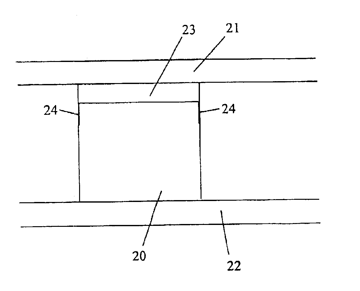
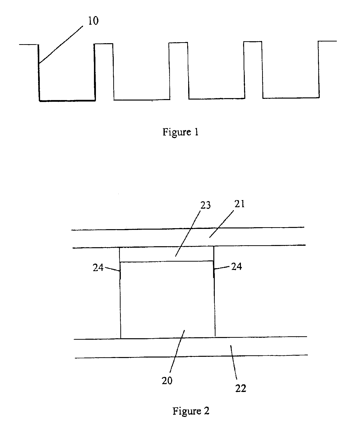
Sheets of microcup used in the following examples were prepared by embossing of an ITO (Indium Tin Oxide) film coated on a 5 mil PET (polyethylene terephthalate) layer. The sheets were plasma treated according to the conditions indicated below.

In addition to the standard colorless microcups, blue and black colored microcups were also prepared to reduce the light leakage.

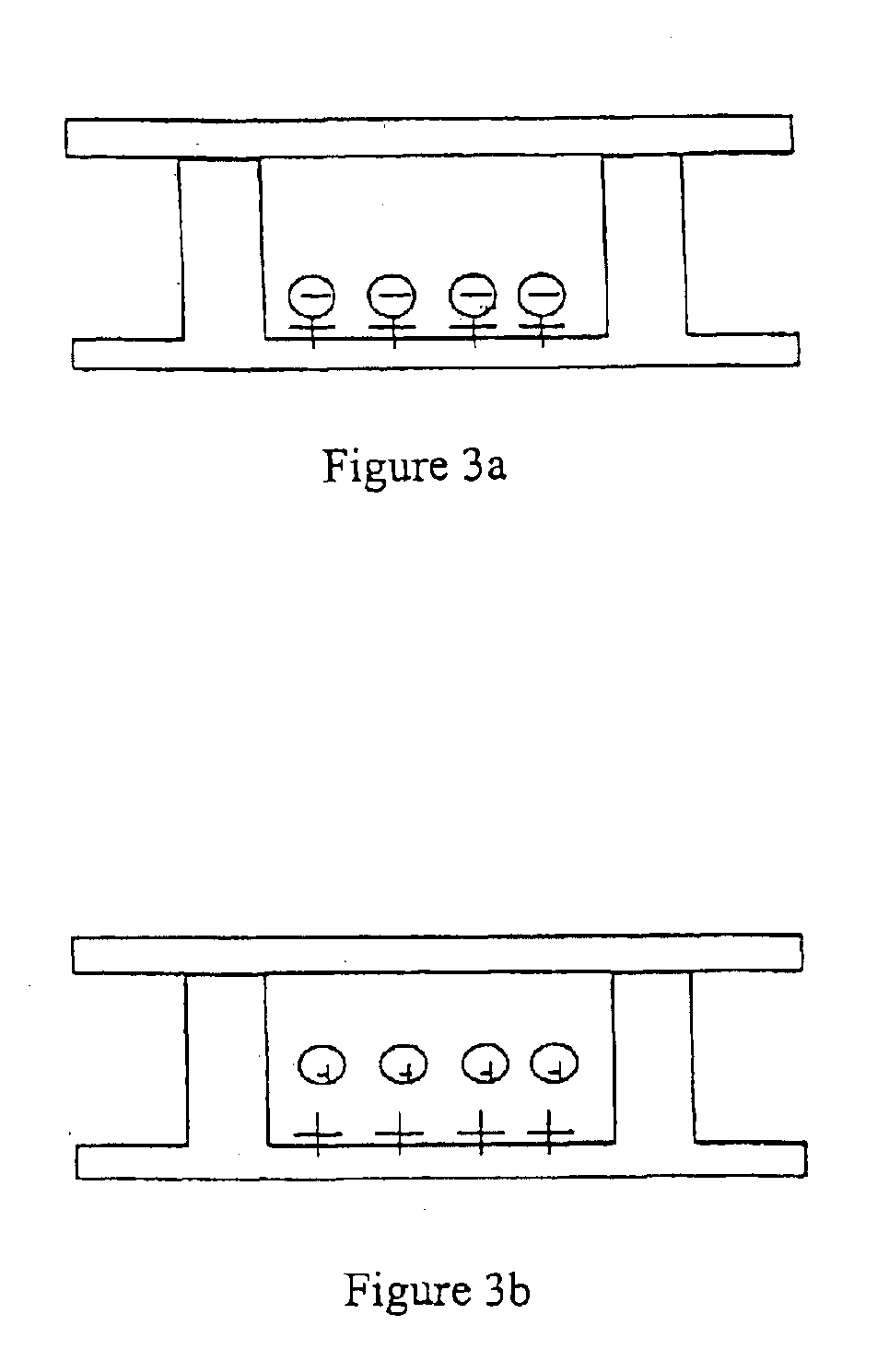
The microcups were then filled with an electrophoretic dispersion, sealed with a polymeric layer and finally laminated with a second electrode plate. All of these preparation steps were carried out according to WO 01 / 67170. For treatment with osmium tetroxide, untreated cup substrates were stored in desiccators and all operations were performed in fume hoods.

examples 1-3

An oxygen plasma was applied first to the surface of the microcups at a flow rate of 250 SCCM under vacuum pressure of 150 mtorr and plasma power of 350 watts, for three minutes.

An acrylic acid plasma was then applied at the rate of 12 ml per hour with the carrier gas, Ar, at a flow rate of 50 SCCM under vacuum pressure of 90 mtorr. The plasma power was applied at 75 watts (Example 1), 100 watts (Example 2), and 125 watts (Example 3), for 5 minutes.

Finally, Ar was applied alone at 800 SCCM under vacuum pressure of 430 mtorr for 3 minutes.

examples 4-7

Ammonia gas was applied to the surface of microcups with carrier gas, Ar, at a flow rate of 25 SCCM. The dosages of the ammonia gas applied were as follows:

ExperimentPowerPressure4400 watts120 mtorr5200 watts120 mtorr6400 watts150 mtorr7200 watts150 mtorr

The application lasted for 5 minutes after which the Ar gas alone was applied under pressure of 525 mtorr for additional 3 minutes.

Results for Plasma Treatments

Table 1 summarizes the performance of colorless microcups treated under the conditions of Experiment 6, compared with that of untreated microcups, at driving voltages of 30V and 50V. The cells were filled with a positively charged pigment dispersion.

TABLE 1DmaxDminContrastWithWithoutWithWithoutWithWithouttreat-treat-treat-treat-treat-treat-mentmentmentmentmentment30 V1.711.620.750.939.124.9050 V1.811.720.750.9311.486.17

Table 2 summarizes the performance of blue colored microcups treated under the conditions of Experiment 2, compared with that of untreated blue colored microcu...


PUM

PropertyMeasurementUnit
temperatureaaaaaaaaaa
dielectric constantaaaaaaaaaa

Abstract

The present invention is directed to methods for improving the performance of an electrophoretic display by modifying the display cell surface. More specifically, the methods are directed to modification of the microcup surface after the microcups are released from the mold. The microcups which have undergone any of the treatment methods of the invention show significant improvement in their surface properties, such as chemical functionality, surface roughness, surface tension, morphology, surface charge, surface reflectivity, surface conductivity and optical properties, particularly optical density in the visible light region. An electrophoretic display formed from the treated microcups has many advantages. For example, the display shows a higher contrast ratio, lower electro-optic response time, lower driving voltage, longer shelf life, higher imageincreasing bistability and higher threshold voltage. In addition, it exhibits an improved image quality by reducing undesirable scum formation or irreversible particle deposition on the microcup surface.

Description

BACKGROUND OF THE INVENTIONAn electrophoretic display (EPD) is a non-emissive device based on the electrophoresis phenomenon influencing charged pigment particles suspended in a colored dielectric solvent. This general type of display was first proposed in 1969. An EPD typically comprises a pair of opposed, spaced-apart plate-like electrodes, with spacers predetermining a certain distance between the electrodes. At least one of the electrodes, typically on the viewing side, is transparent.When a voltage difference is imposed between the two electrodes, the pigment particles migrate by attraction to the plate of polarity opposite that of the pigment particles. Thus, the color showing at the transparent plate, determined by selectively charging the plates, can be either the color of the solvent or the color of the pigment particles. Reversal of plate polarity will cause the particles to migrate back to the opposite plate, thereby reversing the color. Intermediate color density (or sha...

Claims


Application Information

Patent Timeline
Patent Type & Authority Patents(United States)
IPC IPC(8): G02F1/01G02F1/167G02F1/13G02F1/1333G02F1/1679
CPCG02F1/167G02F1/133377Y10T428/24562Y10T428/24479G02F1/1679
Inventor TSENG, SCOTT C-JHOU, JACKWU, ZARNG-ARH GEORGEWANG, XIAOJIALIANG, RONG-CHANG
Owner E INK CALIFORNIA
Why Eureka
Try Eureka