
Optical signal level adjustment system, information analysis/control signal generation apparatus in the same system, and information analysis/control signal generation method

a technology of information analysis/control signal and level adjustment system, which is applied in the field of optical signal level adjustment system, information analysis/control signal generation apparatus in the system, and information analysis/control signal generation method, can solve the problems of complicated circuit configuration and increase cost, and achieve the effect of preventing the deterioration of transmission characteristics and increasing channel power

Active Publication Date: 2011-12-22
NEC CORP
View PDF2 Cites 40 Cited by
  • Summary
  • Abstract
  • Description
  • Claims
  • Application Information

AI Technical Summary

Benefits of technology

[0014]According to the present invention, an increase in the channel power can be prevented at the time of occurrence of a cable disconnection, making it possible to prevent transmission characteristics from deteriorating due to the nonlinear effect in the transmission path.

Problems solved by technology

However, these approaches require complicated circuit configuration and increase cost.

Method used


Image

  • Optical signal level adjustment system, information analysis/control signal generation apparatus in the same system, and information analysis/control signal generation method
  • Optical signal level adjustment system, information analysis/control signal generation apparatus in the same system, and information analysis/control signal generation method
  • Optical signal level adjustment system, information analysis/control signal generation apparatus in the same system, and information analysis/control signal generation method

Examples


Embodiment Construction

[0022]An exemplary embodiment for practicing the present invention will be described in detail below with reference to the accompanying drawings.

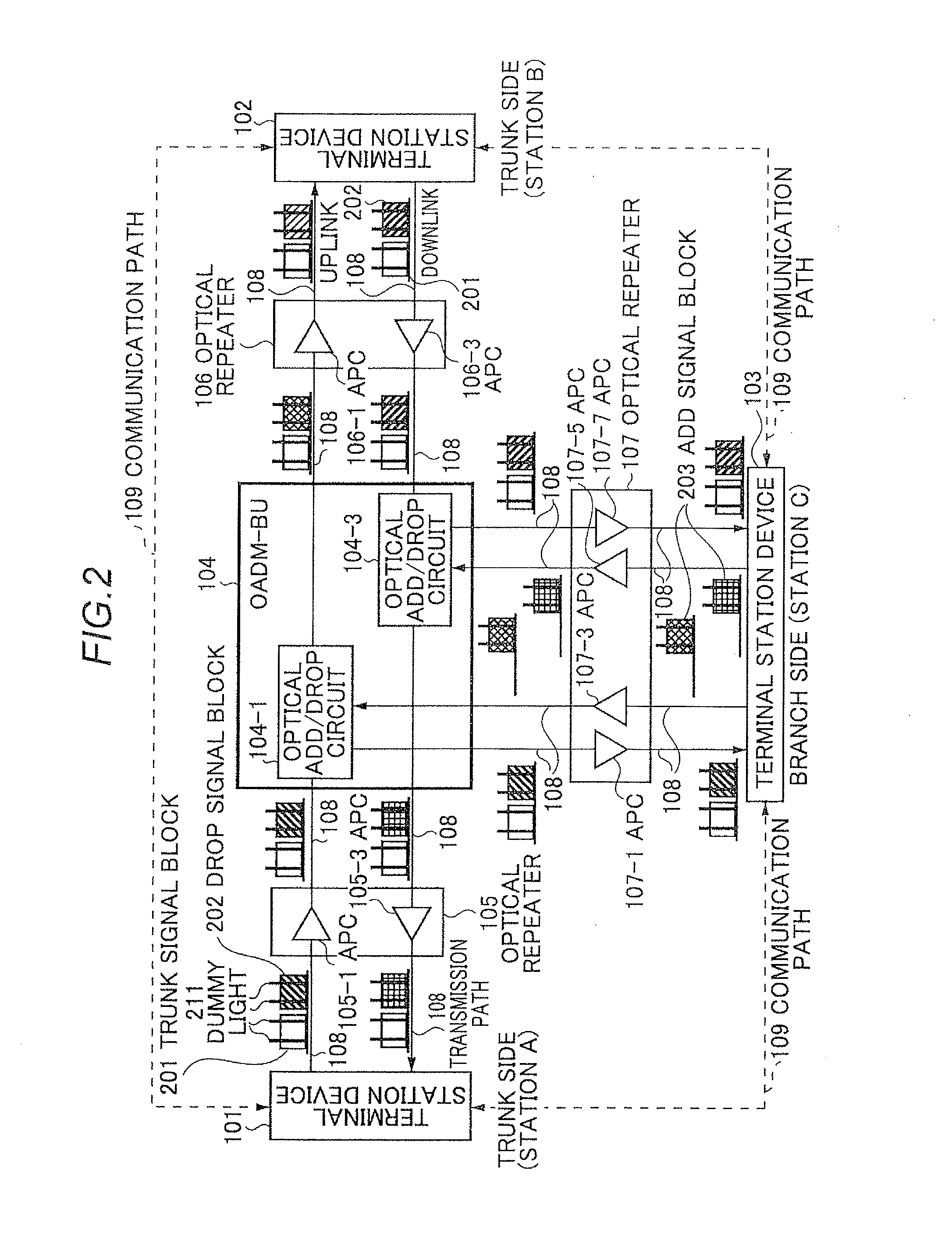
[0023]In a submarine cable system employing an OADM-BU, (1) a dummy light for relieving a main signal at cable disconnection time is disposed in a signal band, and (2) output of the dummy light is adjusted at the time of occurrence of a cable disconnection so as to suppress transmission characteristics of the main signal from deteriorating.

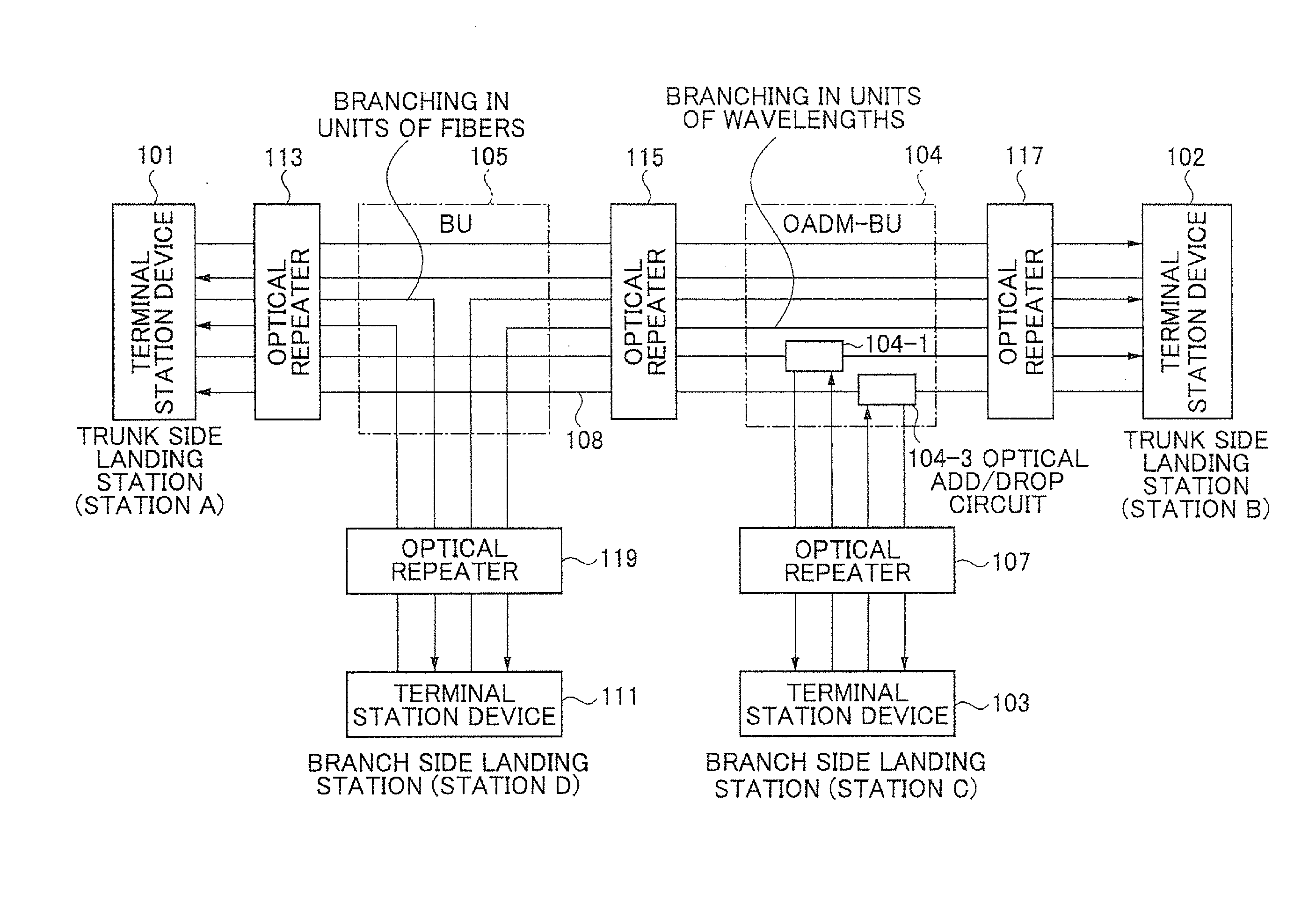
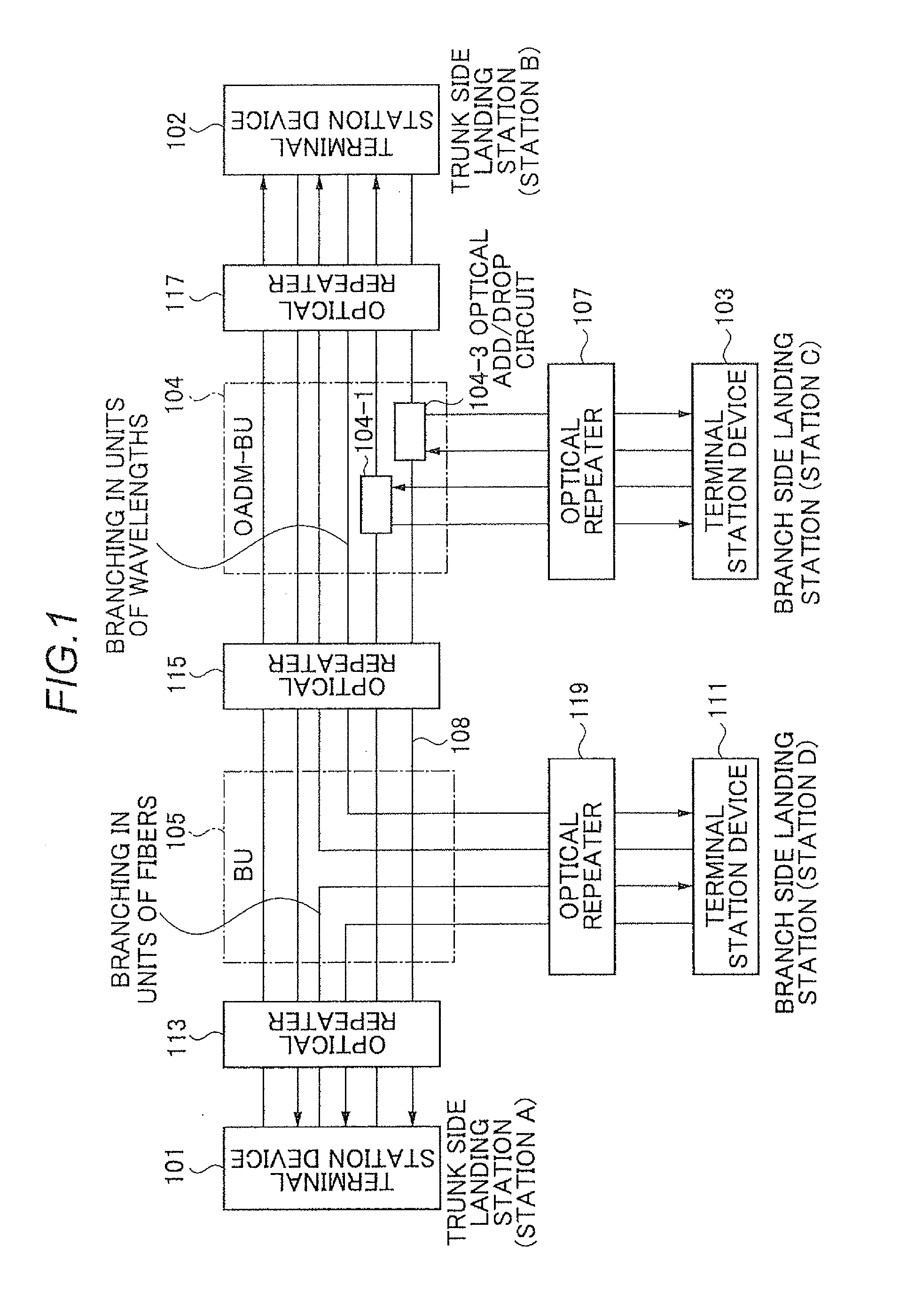
[0024]An optical submarine cable system illustrated in FIG. 1 includes terminal station devices 101, 102, 103, and 111 which are installed in a landing station, and a transmission path 108, optical repeaters 113, 115, 117, 107, and 119, and BUs (Branching Units) 104 and 105 which are laid on the bottom of the sea. Landing stations (station A, station B) 101 and 102 which directly transmit / receive optical signal without branching it are each referred to as “a trunk station”, and landing stations (station C...


PUM


Abstract

The present invention enables to prevent transmission characteristics from deteriorating due to the nonlinear effect in the transmission path caused by an increase in the channel power when a cable disconnection occurs. An optical signal level adjustment method comprises the steps of: obtaining, based on one or more optical signal disconnections which are detected per wavelength block and each of which is detected by a signal disconnection detection section included in each of terminal station devices, a location at which the optical signal disconnection has occurred, a combination of a terminal station device and a wavelength block, and a dummy light adjustment amount, said combination being required to be subjected to adjustment of transmission dummy light, said combination and said dummy light adjustment amount corresponding to the location; and transmitting, to the terminal station device which is required to be subjected to adjustment of the transmission dummy light, a control signal for adjusting the intensity of the dummy light in the obtained wavelength block by the dummy light adjustment amount.

Description

TECHNICAL FIELD [0001]The present invention relates to an optical signal level adjustment system, an information analysis / control signal generation apparatus in the system, and an information analysis / control signal generation method and, more particularly, to an optical signal level adjustment system, an information analysis / control signal generation apparatus in the system, and an information analysis / control signal generation method capable of being applied to an optical submarine cable system and an onshore optical communication system.BACKGROUND ART [0002]In general, in order to achieve channel power management at the cable disconnection time, an optical repeater output is adjusted or a switch circuit is mounted in a BU (Branching Unit). However, these approaches require complicated circuit configuration and increase cost.[0003]Patent Literature 1 discloses a technique in which a dummy light (ASE light) is disposed in a wavelength channel unallocated band, and the power of the ...

Claims


Application Information

Patent Timeline
IPC IPC(8): H04B10/08H04B10/03H04B10/07H04B10/079H04B10/29H04B10/296H04J14/00H04J14/02
CPCH04B10/0791H04J14/0221H04J14/0213H04B10/27
Inventor INOUE, TAKANORI
Owner NEC CORP
Learn More