Microbial desalination cells

a desalination cell and microorganism technology, applied in the direction of filtration separation, other chemical processes, separation processes, etc., can solve the problems of inability to use agricultural irrigation, lack of adequate fresh water, and inability to meet the needs of agricultural irrigation, etc., and achieve the effect of improving the quality of desalination

Inactive Publication Date: 2011-12-22
UMW RES FOUND INC
View PDF6 Cites 21 Cited by
  • Summary
  • Abstract
  • Description
  • Claims
  • Application Information

AI Technical Summary

Benefits of technology

[0006]This disclosure provides microbial desalination cells (MDCs), and desalination processes. Some MDCs disclosed herein include an anode, an anode chamber, an anion exchange material, a cathode, a cation exchange material, a saline solution chamber and a cathode rinsing assembly. The anode is at least partially positioned within the anode chamber for containing an aqueous reaction mixture including one or more organic compounds and one or more bacteria for oxidizing the organic compounds. The cathode is directly exposed to air. The saline solution chamber is positioned between the anode and the cathode, and is separated from the anode by the anion exchange material and from the cathode by the cation exchange material. The cathode rinsing assembly is for rinsing the cathode with a catholyte.

Problems solved by technology

The lack of adequate quantities of fresh water poses a significant global challenge.
About 97% of the Earth's water is seawater, which is non-potable and cannot be used for agricultural irrigation.
The primary source of energy for powering such desalination systems currently comes from fossil fuels, which are expensive, are non-renewable, and have a substantial environmental impact.
However, at the current stage, desalination powered by renewable energy costs more than the methods powered by conventional energy sources, although environmental benefits may balance those costs.

Method used


Image

  • Microbial desalination cells
  • Microbial desalination cells
  • Microbial desalination cells

Examples


example 1

MDC Setup

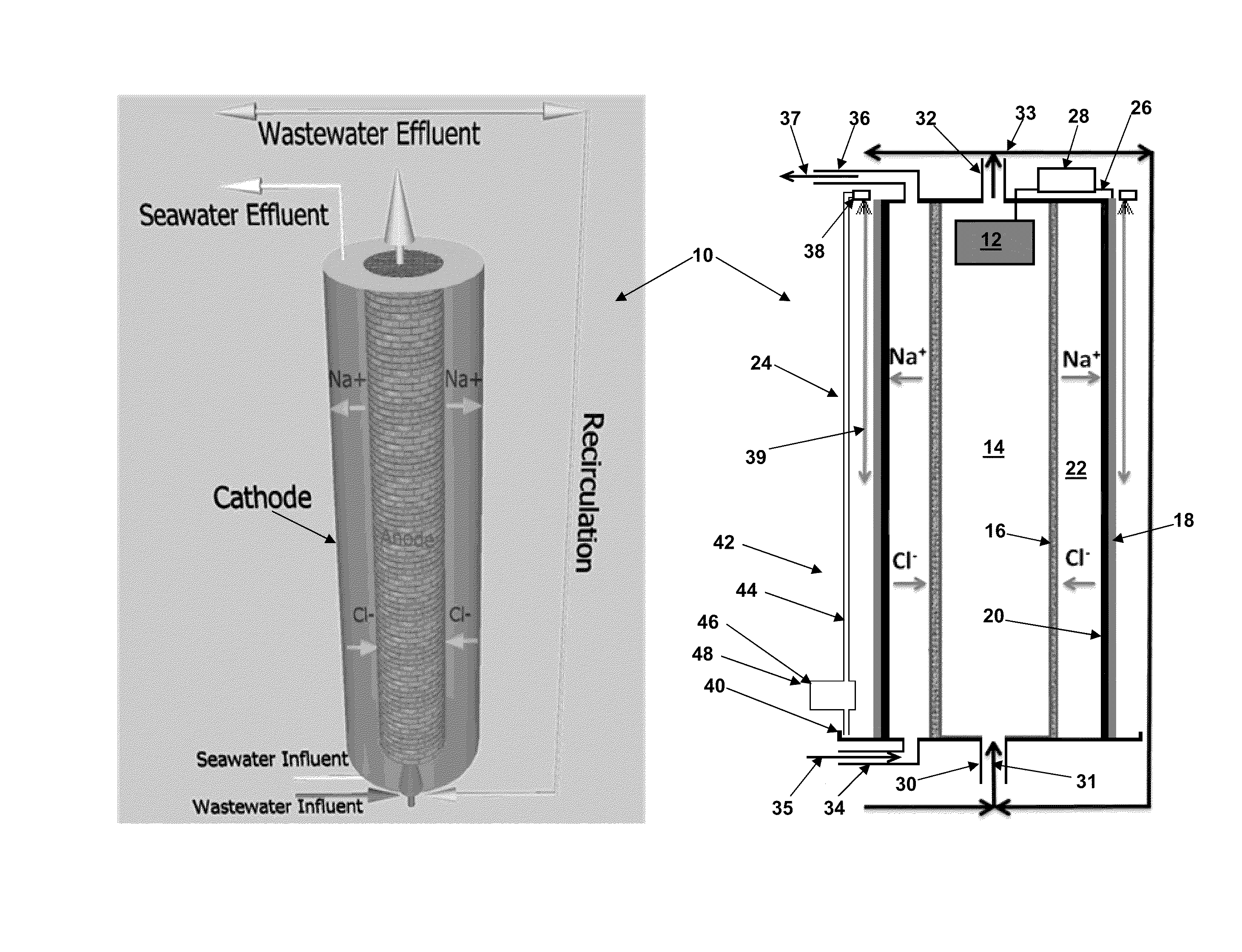
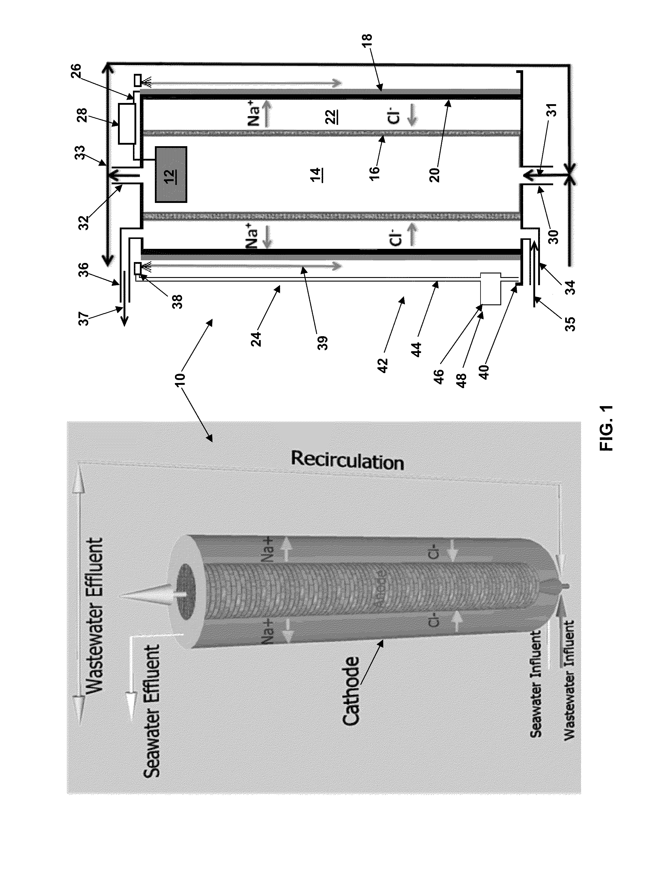
[0064]Two cylindrical MDCs were provided having the general construction shown in FIG. 1. Each MDC 10 included an anode 12, an anode chamber 14, an anion exchange material 16, a cathode 18, a cation exchange material 20 and a saline solution chamber 22. For each of the MDCs, the anion exchange material (AMI-7001, Membrane International Inc., Glen Rock, N.J., USA) had a tubular or cylindrical shape that defined the cylindrical anode chamber and the inner wall of the saline solution chamber. Each cation exchange material (CMI-7000, Membrane International Inc.) surrounded the anion exchange material and had a tubular or cylindrical shape that defined the outer wall of the saline solution chamber. The membrane tubes were sealed using epoxy. The anode chamber included an inlet 30 at the bottom of the anode chamber and an outlet 32 at the top of the anode chamber. Similarly, the saline solution chamber included an inlet 34 at the bottom of the saline solution chamber and an outle...

example 2

Operating Conditions for the First MDC

[0067]The first MDC was operated for more than four months, and it consistently removed salts while generating electricity.

[0068]Synthetic wastewater was prepared by dissolving sodium acetate (4 g / L), NH4Cl (0.15 g / L), NaCl (0.5 g / L), MgSO4 (0.015 g / L), CaCl2 (0.02 g / L), KH2PO4 (0.53 g / L), K2HPO4 (1.07 g / L), yeast extract (0.1 g / L), and trace element (1 mL / L) into tap water. The synthetic wastewater was fed as influent 31 though the anode chamber inlet 30 and into the bottom of anode chamber 14 at a flow rate of about 0.7 mL / min. Effluent 33 was discharged from the top of the anode chamber through the anode chamber outlet 32. The effluent from the anode chamber was recirculated at about 120 mL / min and its HRT was about 12 h. The anode 12 was inoculated with a mixture of aerobic and anaerobic sludge from local wastewater treatment plants (Jones Island Wastewater Treatment Plant and South Shore Wastewater Treatment Plant, Milwaukee, Wis., USA). Th...

example 3

Operating Conditions for the Second MDC

[0073]The second MDC was operated for periods of more than eight months, and it consistently removed salts while generating electricity.

[0074]Synthetic wastewater was prepared by dissolving sodium acetate (3 g / L), NH4Cl (0.15 g / L), NaCl (0.5 g / L), MgSO4 (0.015 g / L), CaCl2 (0.02 g / L), KH2PO4 (0.53 g / L), K2HPO4 (1.07 g / L), yeast extract (0.1 g / L), and trace element (1 mL / L) into tap water. The synthetic wastewater was fed as influent 31 though the anode chamber inlet 30 and into the bottom of the anode chamber 14 at a flow rate of about 4.0 mL / min. Effluent 33 was discharged from the top of the anode chamber through the anode chamber outlet 32. Effluent from the anode chamber was recirculated at about 200 mL / min and its HRT was about 8 h. The anode 12 was inoculated with a mixture of aerobic and anaerobic sludge from local wastewater treatment plants (Jones Island Wastewater Treatment Plant and South Shore Wastewater Treatment Plant, Milwaukee, W...


PUM

PropertyMeasurementUnit
hydraulic retention timeaaaaaaaaaa
temperaturesaaaaaaaaaa

Abstract

A microbial desalination cell includes an anode, a cathode, a saline solution chamber and a cathode rinsing assembly. The anode is at least partially positioned within an anode chamber for containing an aqueous reaction mixture including one or more organic compounds and one or more bacteria for oxidizing the organic compounds. The cathode is directly exposed to air. The saline solution chamber is positioned between the anode and the cathode, and is separated from the anode by an anion exchange material and from the cathode by a cation exchange material. The cathode rinsing assembly is for rinsing the cathode with a catholyte.

Description

REFERENCE TO RELATED APPLICATION[0001]This application claims the benefit of U.S. Provisional Patent Application No. 61 / 355,438, filed Jun. 16, 2010, the content of which is incorporated herein by reference in its entirety.BACKGROUND[0002]The lack of adequate quantities of fresh water poses a significant global challenge. About 97% of the Earth's water is seawater, which is non-potable and cannot be used for agricultural irrigation. Improved methods and systems for desalinating water may be critical for producing fresh water, especially in areas where seawater is abundant, but fresh water is not. Generally, salts can be removed from water using thermal and / or membrane desalination systems, which each require substantial energy. The primary source of energy for powering such desalination systems currently comes from fossil fuels, which are expensive, are non-renewable, and have a substantial environmental impact. Renewable energies, such as solar, wind, hydroelectric and geothermal e...

Claims


Application Information

Patent Timeline
Patent Type & Authority Applications(United States)
IPC IPC(8): H01M8/16C02F3/00C02F103/08
CPCC02F3/005C02F3/341Y02E60/527H01M8/16C02F2001/46133Y02E60/50Y02W10/37
Inventor HE, ZHEN
Owner UMW RES FOUND INC
Why Eureka
Try Eureka