However, many chronically implanted
catheter systems are often plagued with reduced performance due to the prolonged accumulation of biological debris.
For the
neurological disorder of
hydrocephalus, obstruction of the shunt tubing that diverts
cerebrospinal fluid (CSF) from the brain is one of the most commonly occurring complications, which can result in a catastrophic shunt failure that could inflict serious bodily harm to the patient.
A malfunctioning (or obstructed) shunt can be a life-threatening condition.
Each successive shunt revision may cause brain injury and increases the risk of shunt infection.
Not only are shunt-replacement surgeries a cause of morbidity and stress for patients and families, but they also impose economic burdens on the patient and society.
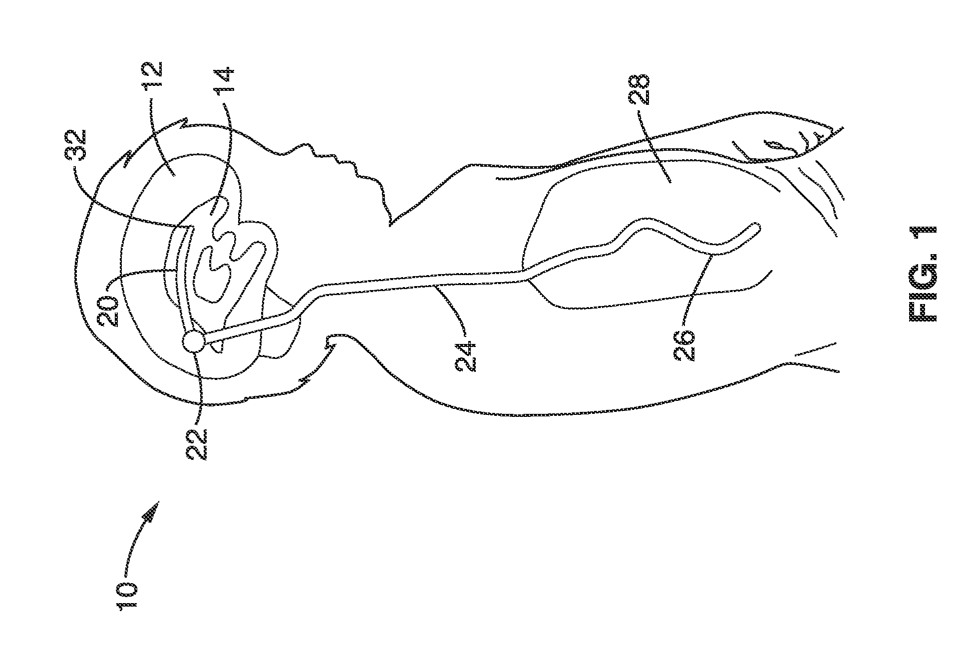
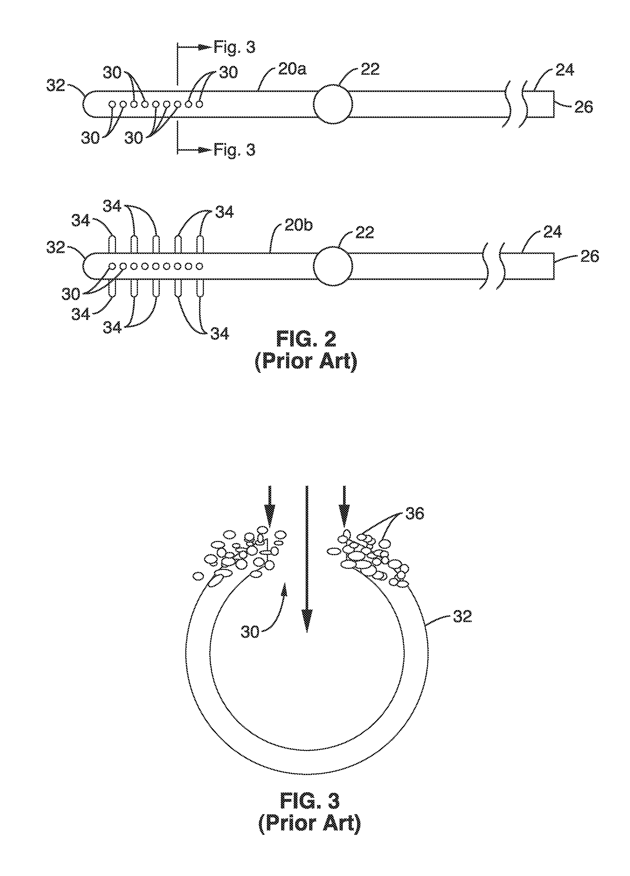
1. Gradual accumulation of cells in flow pores: FIG. 2 illustrates a currently available ventricular shunt
system using a ventricular catheter 20 having a plurality of intake pores 30 at end 32 of the catheter. As seen further in the cross-sectional view of FIG. 3, cells 36 may accumulate in and around intake pore 30 to partially and then fully occlude the opening 30.
Hydrocephalus often results in an increased numbers of cells in the patients' CSF (pleocytosis). Similar
pathology can be found in patients with chronic
meningitis, and it is thought to be one of the main causes of shorter shunt half-lives for these patients. Indeed, non-pleocytic CSF does have lower cellular concentration. However, even in
hydrocephalus patients without pleocytosis, the shunt
system moves hundreds of millions of cells to through its catheter pores in its lifetime such that the cellular
occlusion is almost a certain eventuality. As such, the cellular
occlusion is thought to be one of the main causes of shunt malfunction in
hydrocephalus patients.
2. Ventricular collapse due to excess drainage: Ventricular collapse following
shunting procedures has been associated with shunt obstruction. A primary focus of valve 22 design has been to limit excessive drainage and therefore prevent the collapse of the ventricles 14. Although the incorporation of valves with an adjustable opening
differential pressure that control the rate of CSF flow have been touted to maintain an ideal ventricular size and
intracranial pressure, these goals have not been consistently achieved clinically. The mechanism by which obstruction occurs with ventricular collapse is related to the direct
apposition of ependymal and / or
choroid plexus tissue with the ventricular catheter tip. The close proximity to the ependymal wall provides abundant supply of cells to accumulate on the ventricular catheter pores. Despite advances in valve technologies, ventricular collapse continues to be an
increased risk of shunt obstruction.
3.
Choroid plexus tissue migration and ingrowth:
Choroid plexus tissue migration occurs in situations where the catheter flow holes are in close proximity with the
choroid. The suctioning effect, which is inherent in many shunt designs, can draw the
choroid tissue directly into the catheter pores. FIG. 2 shows a prior art flanged catheter tip 20b having a plurality of radial flanges 34 at the site of the apertures 30, which was introduced with the goal of preventing the choroid tissue from accessing the flow holes 30. The clinical experience with this design, however, has been mixed. Proximal catheter obstructions have not been prevented and the reason is not clear. Assuming choroid tissue was indeed impeded, cells freely floating in CSF presumably led to the obstruction. Some studies have suggested that optimal placement of the catheter tip is at a location that is out of the reach of the
choroid plexus. Anatomically, this placement goal is very difficult to achieve with current catheter designs. With better catheter designs and judicious use of
endoscopy, this placement goal may be achieved.
Cellular
occlusion is thought to be one of the main causes of failure for the chronically implanted catheters in hydrocephalus patients.
Red blood cells, however, are susceptible to coagulation, which could result in larger body of
mass that may ultimately obstruct catheter pores.
Biomedical approaches, such as use of a
silicone elastomer,
grafting, hydrophilic, lubricious hydrogel onto the
silicone surface, and
drug-eluting catheters, have yet to display consistent performance over long period of time.
However, one major caveat of this approach is that the device must reside within the catheter pore, and thus is prone to cause additional hindrance to the normal flow of CSF.

