Photoelectric gas sensor device and manufacturing method thereof

a gas sensor and photoelectric technology, applied in the direction of material analysis, material analysis using wave/particle radiation, instruments, etc., can solve the problem of weak signal reception in the conventional optical sensor, and achieve the effect of improving selectivity and signal reception strength, and being easy and more cost-effectiv

Inactive Publication Date: 2011-12-29
UNIMEMS MFG +1
View PDF9 Cites 0 Cited by
  • Summary
  • Abstract
  • Description
  • Claims
  • Application Information

AI Technical Summary

Benefits of technology

[0010]An object of the instant disclosure is to provide a photoelectric gas sensor device and a manufacturing method thereof. Particularly, the instant disclosure provides an easier and more cost-effective method of producing a photoelectric gas sensor device that has improved selectivity and signal reception strength. Furthermore, the receiver assembly of the instant photoelectric gas sensor may be fine-tuned to uniformly receive energy from the emitter assembly.

Problems solved by technology

When a harmful gas is present, the gas molecules may absorb or deflect the infrared light emitted from the light source.
However, the average incidental angle of the incoming energy beams to the conventional optical sensor is too large, resulting in weak signal reception in the conventional optical sensors.

Method used


Image

  • Photoelectric gas sensor device and manufacturing method thereof
  • Photoelectric gas sensor device and manufacturing method thereof
  • Photoelectric gas sensor device and manufacturing method thereof

Examples


Embodiment Construction

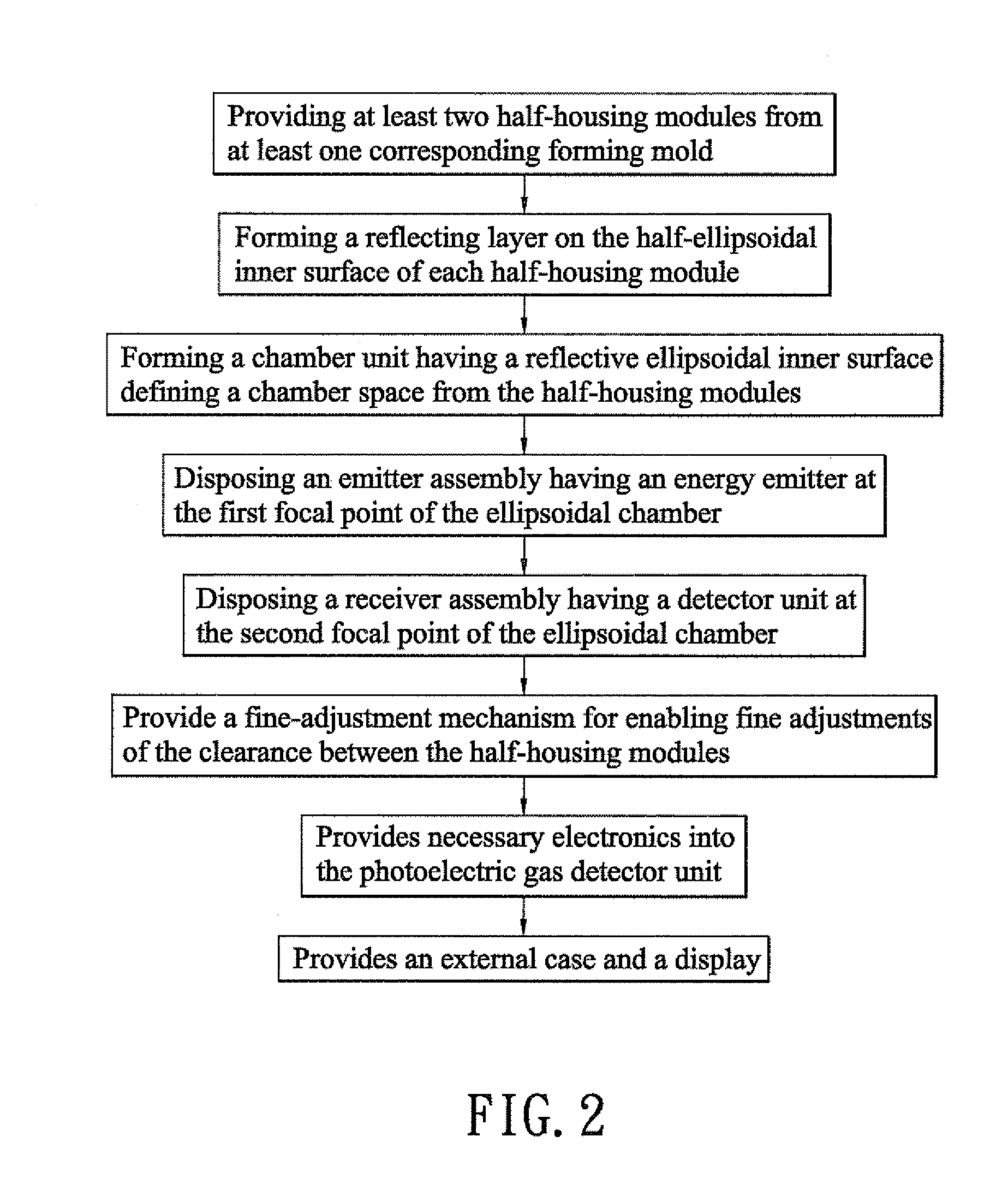
[0025]To achieve the objective of providing a photoelectric gas sensor device according to the instant disclosure (such as illustrated in FIG. 7-9), a flow chart comprising detailed manufacturing steps is provided in FIG. 2.

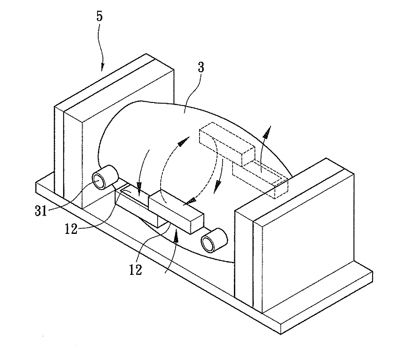
[0026]Referring to FIG. 2, the manufacturing method comprises the following steps. (1) Providing at least two half-housing modules 1 from at least one corresponding forming mold (as shown in FIG. 3). Each half-housing module may include at least one half-convection-opening 11 or a half-diffusion-opening 12; at least one protruding joint 13; at least one recessing slot 14; and a substantially half-ellipsoidal inner surface formed thereon. In the instant embodiment, half-housing module 1 comprises a pair of half-diffusion-openings 12, a pair of half-convection-openings 11, a pair of protruding joint 13 and recessing slot 14. However, the number of these elements may be configured differently to fit specific operational requirements. The half-housing module 1 may be...


PUM

PropertyMeasurementUnit
energyaaaaaaaaaa
shapeaaaaaaaaaa
ellipsoidal shapeaaaaaaaaaa

Abstract

The instant disclosure provides a photoelectric gas sensor device and a manufacturing method thereof. The manufacturing method comprising the steps of: (A) providing at least two half-housing modules from at least one corresponding mold; (B) forming a reflecting layer on the ellipsoidal inner surface of the chamber unit; (C) forming a chamber unit having a reflective ellipsoidal inner surface defining a chamber space from the half-housing modules; (D) forming a reflecting layer on each inner surface of the two half-housings; and (E) disposing an emitter assembly having an energy emitter at the first focal point of the ellipsoidal chamber. A fine-adjustment mechanism may be further provided to enable clearance adjustment between the half-housing modules.

Description

BACKGROUND OF THE INVENTION[0001]1. Field of the Invention[0002]The present invention relates to a gas sensor device and a manufacturing method thereof, and particularly to a photoelectric gas sensor device and a manufacturing method thereof.[0003]2. Description of Related Art[0004]Many types of gas sensors are developed to detect toxic, flammable, explosive, or asphyxiant gases harmful to human body. Common types of gas sensors include electrochemical gas sensors, solid electrolyte gas sensors, semiconductor gas sensors, and optical gas sensors. While the underlying principles behind different types of detectors may be different, the development emphasis and performance requirements, such as high sensitivity, low manufacturing cost, good selectivity, quick reaction, high stability and repeatability, remain the same.[0005]The electrochemical gas sensor detects a gas by dissolving the gas in a liquid electrolyte to trigger an oxidation-reduction reaction and measuring the variation i...

Claims


Application Information

Patent Timeline
Patent Type & Authority Applications(United States)
IPC IPC(8): G01N21/17H05K13/00
CPCG01N21/05Y10T29/49002G01N21/3504
Inventor LEE, TZONG-SHENG
Owner UNIMEMS MFG
Why Eureka
Try Eureka