Micro-Gap Thermal Photovoltaic Large Scale Sub-Micron Gap Method and Apparatus

a thermal photovoltaic and micro-gap technology, applied in thermal-pv hybrid energy generation, pv power plants, semiconductor devices, etc., can solve the problems of uncontrollable power output variance, temperature increases, and obstacles to its practical use, and achieve the effect of convenient manufacturing

Active Publication Date: 2011-12-29
MTPV POWER CORP
View PDF9 Cites 14 Cited by
  • Summary
  • Abstract
  • Description
  • Claims
  • Application Information

AI Technical Summary

Benefits of technology

[0013]It is therefore an object of this invention to provide a novel micro...

Problems solved by technology

The amount of power out of a given TPV device area is constrained by the temperature of the hot side of the device and generally requires very high temperatures, creating barriers to it practical use.
While it is possible to obtain the sub-micron gap spacing, the thermal effects on the hot and cold surfaces induce cupping, warping, or deformat...

Method used


Image

  • Micro-Gap Thermal Photovoltaic Large Scale Sub-Micron Gap Method and Apparatus
  • Micro-Gap Thermal Photovoltaic Large Scale Sub-Micron Gap Method and Apparatus
  • Micro-Gap Thermal Photovoltaic Large Scale Sub-Micron Gap Method and Apparatus

Examples


embodiment 200

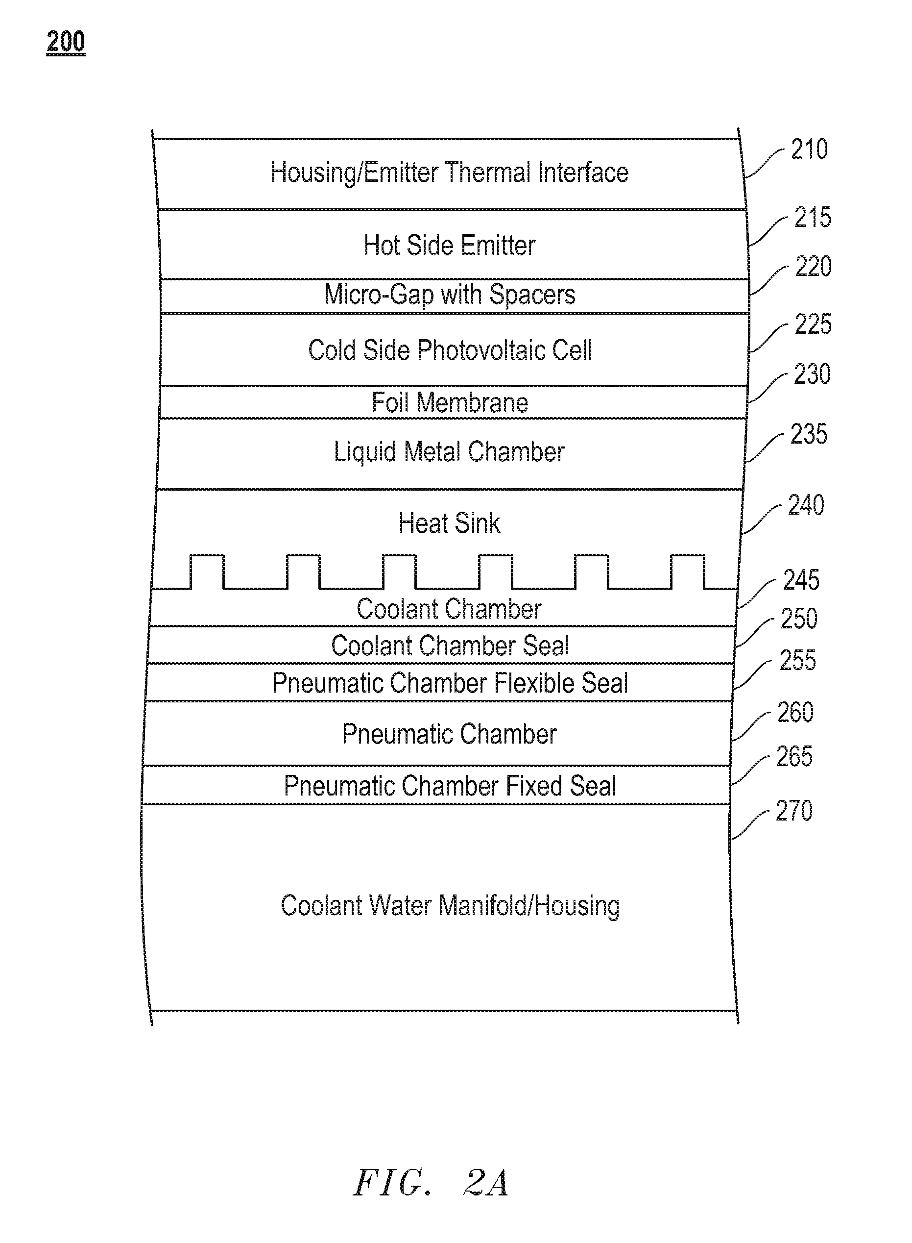
[0048]Turning to FIG. 2A, FIG. 2A illustrates an embodiment 200 of a single-sided MTPV device. The embodiment includes a thermal interface 210 for conducting heat between housing that is exposed to a high temperature and a hot side emitter 215. The hot side emitter 215 is separated from a cold side photovoltaic cell 225 by a micro-gap that is maintained by spacers 220. A foil membrane 230 is positioned between the cold side photovoltaic 225 and a chamber 235 containing a liquid metal that is maintained under controlled pressure. This pressurized chamber 235 ensures that the hot side emitter 215 and thermal interface 210 is maintained in close contact with the housing over a wide temperature range. Adjacent to the liquid metal chamber 235 is a heat sink 240 that is cooled by a continuous flow of coolant in a coolant chamber 245. The coolant chamber 245 is separated from a pneumatic chamber 260 by a coolant chamber seal 250 and a pneumatic chamber flexible seal 255. The pneumatic cham...

embodiment 205

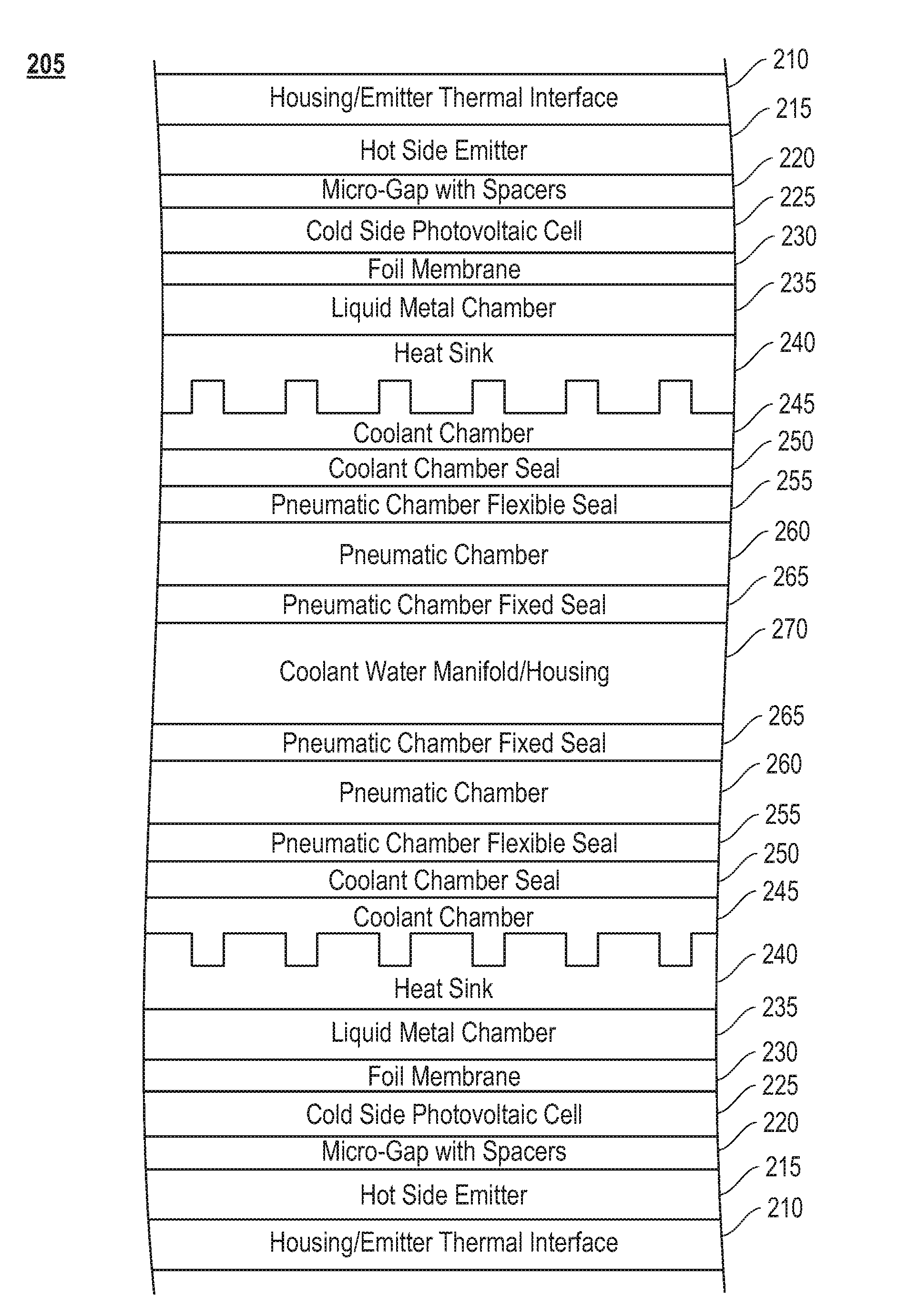
[0049]Turning to FIG. 2B, FIG. 2B illustrates an embodiment 205 of a two-sided MTPV device. The two-sided MTPV device includes the structure described above in relation to FIG. 2A and an additional structure that is an inverted image of that shown in FIG. 2A attached to the common coolant water manifold 270. This structure enables the collection of heat from both sides of an MTPV device.

embodiment 300

[0050]Turning to FIG. 3, FIG. 3 illustrates an embodiment 300 that shows the operation of the MTPV device. The MTPV device 305 is exposed to radiant and convective heat flux 310, which heats the outer surface and the hot side of the hot side / cold side pair 320, 330. A vacuum is maintained in the interior of the MTPV device 305 and the cold side photovoltaic cell is cooled from the inside by circulating water 340, 350. Output power 360, 370 is obtained from the device 305.


PUM


Abstract

The present invention relates to micron-gap thermal photovoltaic (MTPV) technology for the solid-state conversion of heat to electricity. The problem is forming and then maintaining the close spacing between two bodies at a sub-micron gap in order to maintain enhanced performance. While it is possible to obtain the sub-micron gap spacing, the thermal effects on the hot and cold surfaces induce cupping, warping, or deformation of the elements resulting in variations in gap spacing thereby resulting in uncontrollable variances in the power output. A major aspect of the design is to allow for intimate contact of the emitter chips to the shell inside surface, so that there is good heat transfer. The photovoltaic cells are pushed outward against the emitter chips in order to press them against the inner wall. A high temperature thermal interface material improves the heat transfer between the shell inner surface and the emitter chip.

Description

[0001]This application claims benefit of U.S. Provisional Application No. 61 / 308,972 filed on Feb. 28, 2010, and is incorporated herein by reference.FIELD OF THE INVENTION[0002]The present invention relates to micron-gap thermal photovoltaic (MTPV) technology for the solid-state conversion of heat to electricity. More broadly, the invention generates electrical power when it is inserted into a high temperature environment such as an industrial melting furnace.BACKGROUND OF THE INVENTION[0003]Thermo photovoltaic devices (TPV) consist of a heated black-body which radiates electromagnetic energy across a gap onto a photovoltaic device which converts radiant power into electrical power. The amount of power out of a given TPV device area is constrained by the temperature of the hot side of the device and generally requires very high temperatures, creating barriers to it practical use. By contrast, micron gap thermal photovoltaic (MTPV) systems allow the transfer of more power between the...

Claims


Application Information

Patent Timeline
IPC IPC(8): H01L31/052
CPCH01L31/0406H01L31/024H02S10/30H01L31/052H01L31/0521Y02E10/52H01L31/0547H02S40/44H10N10/00H01L31/042Y02E10/60Y02E10/50
Inventor BROWN, ERIC L.DIMATTEO, ROBERT S.NARDELLI, BRUNO A.PENG, BINLI, XIAO
Owner MTPV POWER CORP
Why Eureka
Try Eureka