
Tripod with an automatic height-adjuster

Inactive Publication Date: 2011-12-29
HILTI AG
View PDF26 Cites 20 Cited by
  • Summary
  • Abstract
  • Description
  • Claims
  • Application Information

AI Technical Summary

Benefits of technology

[0008]It is an object of the present invention to put forward a tripod that can be adjusted from an actual position into a target position by one single operator. In order for the tripod to be easy to handle and transport, the tripod should also be compact and resistant to external influences.
[0009]According to the invention, an automatic height-adjustment means or automatic height-adjuster is provided for adjusting the height of the guiding device. Automatic height adjustment has the advantage over manual height adjustment that the operator can set the height from a remote location using a remote control. While the operator holds a laser receiver in the laser beam and reads off the difference between the actual position and the target position, he can use the remote control to adjust the height of the tripod.
[0010]Preferably, the height-adjustment means is arranged on the underside of the tripod head facing the tripod legs. This arrangement of the height-adjustment means translates into a compact structure for the tripod during transportation since there is no need for additional space for the height-adjustment means.
[0012]The tripod head and / or the articulated joints are preferably at least partially made of a material that has a higher energy-absorption capacity than a housing that surrounds the height-adjustment means. In case of a fall, most of the energy is absorbed by the tripod head and by the articulated joints, so that the risk of damage to the height-adjustment means is reduced.
[0013]In a preferred embodiment, the height-adjustment means has a drive unit that interacts with the guiding device, and an overload-protection device, said overload-protection device uncoupling the guiding device from the drive unit if a maximum load is exceeded. The drive unit especially preferably consists of an electric motor and a self-locking reduction gear that interacts with a guiding device configured as a toothed rack. In case of a fall, the overload-protection device, which is integrated as a friction clutch into the reduction gear, ensures that the self-locking of the reduction gear is switched off, so that the toothed rack can move relative to the height-adjustment means. As a result, damage to the drive unit and / or to the guiding device is prevented or at least reduced.

Problems solved by technology

The prior art tripods with a manual height-adjustment means have the drawback that, especially when the work is performed outdoors where the visibility is limited, the tripod cannot be set to the desired height, designated below as the target position, by one operator alone and a second person is necessary.

Method used


Image

  • Tripod with an automatic height-adjuster
  • Tripod with an automatic height-adjuster
  • Tripod with an automatic height-adjuster

Examples


Embodiment Construction

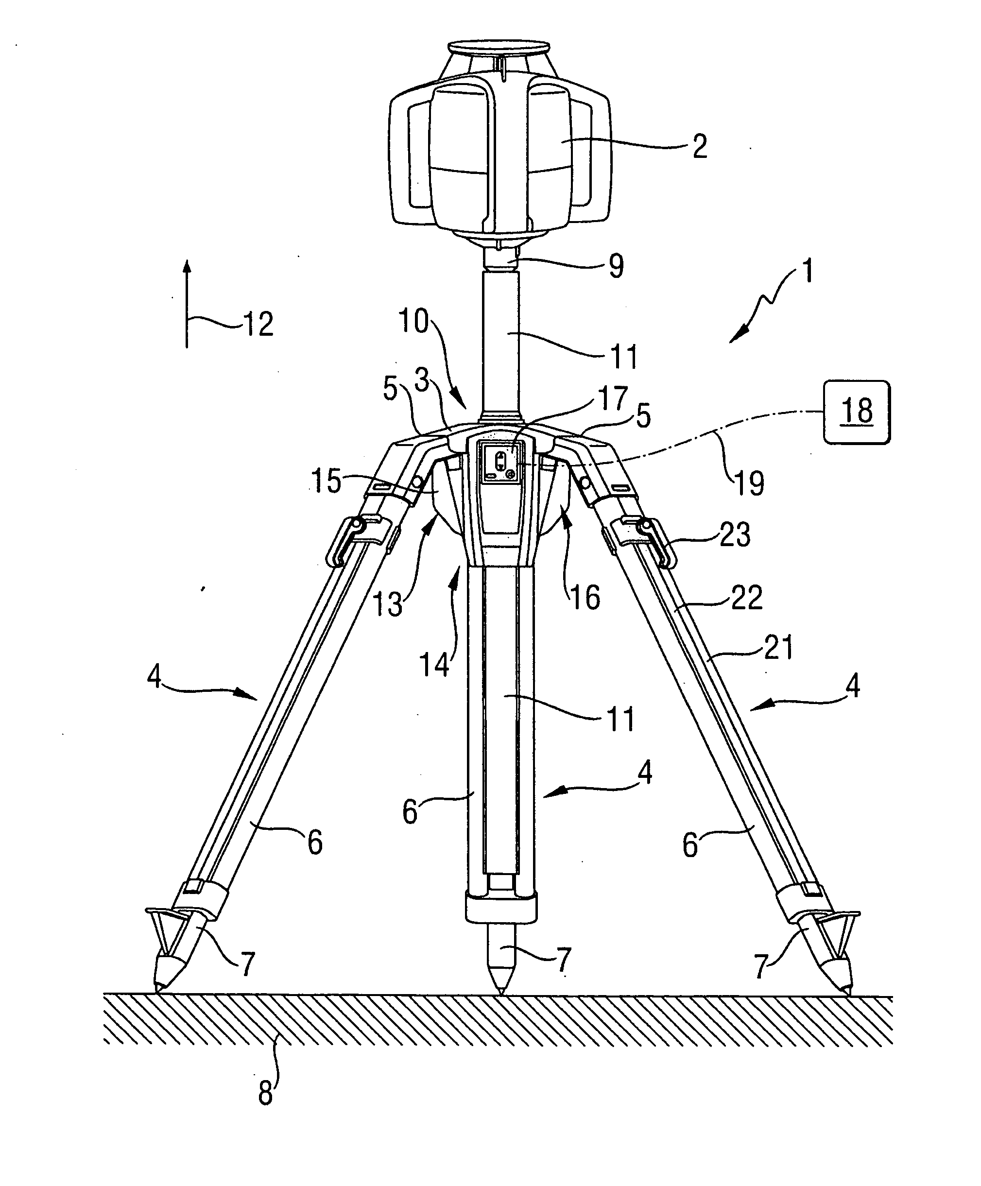
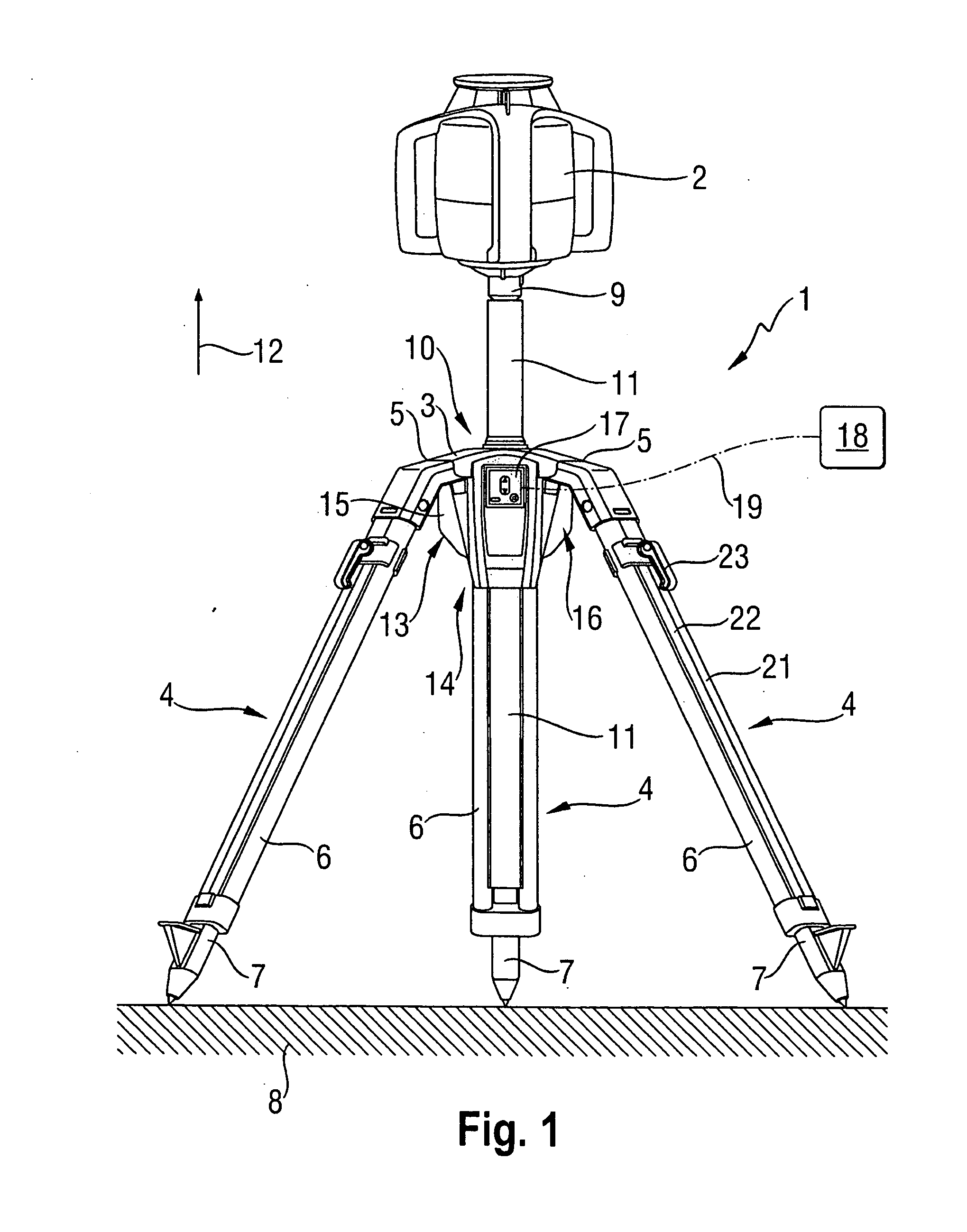
[0021]FIG. 1. shows a tripod 1 according to the invention that has an automatic height-adjustment means and that is arranged in a standing position, with a laser device 2 attached to the tripod 1. The tripod 1 is configured so as to be adjustable between the standing position in which the laser device 2 can be employed for leveling and marking work, and a transport position that serves for the transportation and storage of the tripod 1. Aside from laser devices, other measuring devices or optical instruments such as cameras, which all fall under the designation “device”, can be attached to the tripod 1.

[0022]The tripod 1 comprises a tripod head 3 and three tripod legs 4 that are configured so as to be identical and connected to the tripod head 3 by means of articulated joints 5. The tripod legs 4 can be swiveled relative to the tripod head 3 within an angular range by means of the articulated joints 5. The tripod legs 4 consist of an upper leg section 6, which is configured as a tub...


PUM


Abstract

A tripod (1) for the automatic height adjustment of a device (2) in a height direction (12), including a tripod head (3), tripod legs (4) that are connected to the tripod head (3), a receiver (9) to receive the device (2), and a guide (11) that is connected to the receiver (9) and that can be adjusted in the height direction (12), wherein an automatic height-adjuster (13) is provided for adjusting the height of the guide (11).

Description

[0001]This claims the benefit of German Patent Application DE 10 2010 030 592.8, filed Jun. 28, 2010 and hereby incorporated by reference herein.[0002]The invention relates to a tripod for the automatic height adjustment of a device in a height direction.BACKGROUND[0003]For purposes of carrying out leveling and marking work indoors as well as outdoors, laser devices are known that generate punctiform and / or linear laser beams. The laser beams serve to show reference points or reference lines on walls, ceilings and floors. When it comes to such laser devices, a distinction is made between rotation lasers, which generate a linear laser beam by rotating a source of laser beams or a beam-deflecting lens system around an axis of rotation, and punctiform and / or linear lasers, which generate punctiform and / or linear laser beams by means of beam-forming lens systems such as cylindrical lenses and prisms.[0004]In order to project a laser beam onto a wall at a certain height, the laser device...

Claims


Application Information

Patent Timeline
IPC IPC(8): F16M11/24
CPCF16M11/18F16M11/046F16M2200/027F16M11/36F16M11/16
Inventor LUKIC, SASHAAMMANN, MANFREDEMBERGER, HOLGER MAXWINTER, ANDREASJOHN, ANDREAS
Owner HILTI AG
Features
  • Generate Ideas
  • Intellectual Property
  • Life Sciences
  • Materials
  • Tech Scout
  • Unparalleled Data Quality
  • Higher Quality Content
  • 60% Fewer Hallucinations
Learn More