Intra-oral tissue conduction microphone

a tissue conduction microphone and tissue technology, applied in the field of intraoral sensors, can solve the problems of reduced speech intelligibility, low sensitivity of boom microphones, and easy observation of bulky equipment, and achieve the effect of high sensitivity

Inactive Publication Date: 2011-12-29
SOUNDMED LLC
View PDF4 Cites 36 Cited by
  • Summary
  • Abstract
  • Description
  • Claims
  • Application Information

AI Technical Summary

Benefits of technology

[0013]When clamped to a curved open frame structure, PVDF film provides very high sensitivity to normally directed mechanical displacement and its frequency response is flat when operated below resonance. The curvature translates normally directed pressure into tensile stresses along the film axis that can be much larger than the applied stress. The induced film strain generates charge on the film electrodes in proportion to the applied pressure. Film thickness, radius of curvature (ROC) and electrode area may be adjusted to affect electrical impedance, sensitivity, resonance frequency and mechanical impedance, thus allowing fine tuning to the application.

Problems solved by technology

The study also found speech intelligibility inferior to the boom microphone, due in theory to reduced information encoded from soft articulators such as the tongue and lips.
However, in environments where excessive ambient noise or equipment restrictions, such as full head helmets, protective suits and underwater equipment, preclude use of an air-conducted microphone, reduced speech intelligibility clearly may be tolerated, as numerous contact microphone systems are commercially marketed.
This equipment can be bulky and easily observable, interfere with other equipment such as helmets and protective gear, may occlude the ear canal and may not be used in wet and / or harsh environments.
However, a significant drawback is that a surgical procedure is required to install or remove the microphone, battery and signal conditioning / amplification electronics and there must be some means to externally charge the implanted battery.
Additionally, the implanted microphone relies on several media conversion stages between vibrations at the skin surface and the electrical signal, limiting overall device performance.

Method used


Image

  • Intra-oral tissue conduction microphone
  • Intra-oral tissue conduction microphone
  • Intra-oral tissue conduction microphone

Examples


Embodiment Construction

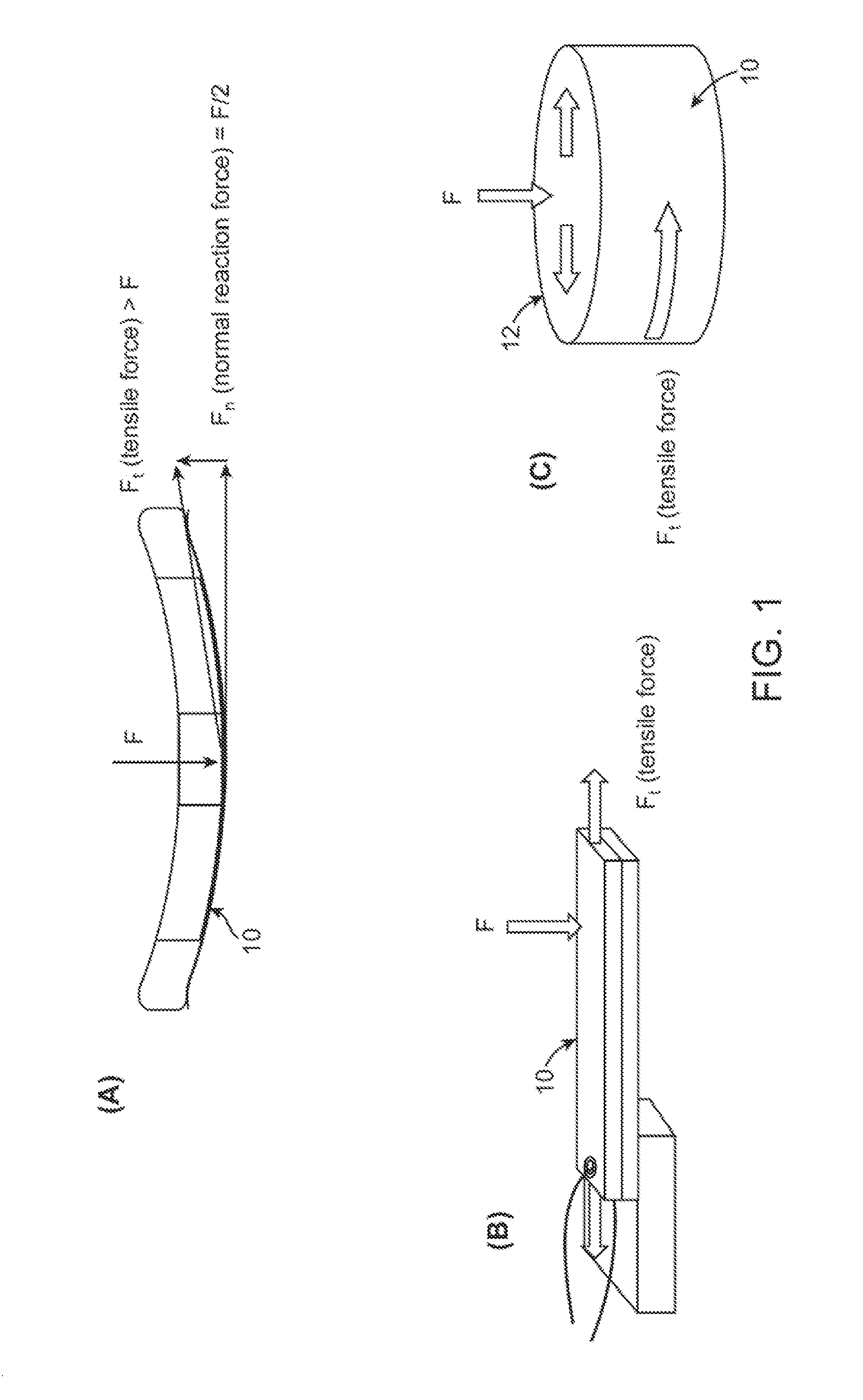
[0035]In contrast to the subcutaneously-implanted microphone, which detects mechanical vibrations of the overlying (tissue) membrane much as an air-conducted microphone does, an intra-oral microphone used for ambient sound detection must respond to sound pressure waves that couple to and propagate through the soft tissue of the head. The air / tissue boundary of the head acts as a significant barrier to sound transmission due to impedance mismatch and scattering of the signal and only a small portion of the external sound pressure energy is transmitted to the embedded sensor. Normal incidence of a pressure wave at an air / water boundary results in a theoretical loss of 33 dB (99.9%) in acoustic intensity. Scattering effects also come into play and FEA models for a sphere of water in air (approximating the head) predict slightly higher acoustic attenuation.

[0036]Therefore an intra-oral tissue conduction microphone used for measuring ambient sound must have sufficient SNR (signal to nois...


PUM


Abstract

Intra-oral tissue conduction microphone apparatus and methods are described for internal, but non-surgically installed microphones located in the oral cavity. An intra-oral tissue conduction microphone may be attached, adhered or integrated with a removable dental appliance which is positioned against the inside surfaces of the cheek, palate or gingiva. The sensor serves as a component in a non-observable hearing, body sound monitoring or communications device that can operate in environments incompatible with most existing devices. Generally, a piezoelectric film serves as the sensor that is well matched to tissue and which directly converts to an electrical signal by the piezoelectric effect signals which are received through the oral mucosa, gingiva or palate.

Description

CROSS-REFERENCE TO RELATED APPLICATIONS[0001]This application claims the benefit of priority to U.S. Prov. App. 61 / 349,508 filed May 28, 2010, which is incorporated herein by reference in its entirety.FIELD OF THE INVENTION[0002]The present invention relates to methods and apparatuses for intra-oral sensors for detection of tissue-conducted vibrations generated by audible or biophysical sounds which may be employed in hearing devices, systems for physical or health monitoring or communications devices.BACKGROUND OF THE INVENTION[0003]Tissue contact vibration sensors (contact microphones) have been widely employed in electronic stethoscopes for sensing sounds originating from the body, such as the heart beat, blood flow or respiration. These sensors (or transducers) are placed in contact with the skin or soft tissue and generate an electrical signal in response to vibrations propagating through the tissue induced by biophysical processes. Another type of electronic stethoscope in wid...

Claims


Application Information

Patent Timeline
Patent Type & Authority Applications(United States)
IPC IPC(8): H04W88/00H04R1/00
CPCH04R1/46H04R17/02H04R1/08
Inventor PROULX, TIMOTHY L.KASSAYAN, REZA
Owner SOUNDMED LLC
Why Eureka
Try Eureka