
Sensor systems having multiple probes and electrode arrays

Active Publication Date: 2011-12-29
MEDTRONIC MIMIMED INC
View PDF3 Cites 225 Cited by
  • Summary
  • Abstract
  • Description
  • Claims
  • Application Information

AI Technical Summary

Benefits of technology

[0008]Embodiments of the invention disclosed herein comprises sensor systems having architectures that include multiple in vivo probes and electrode arrays as well as algorithms designed for use with such systems. Such embodiments of the invention can be used to enhance sensor accuracy and reliability and overcome a number of technical challenges observed in this field. One illustrative embodiment is an amperometric analyte sensor system comprising a probe platform; a first probe coupled to the probe platform and adapted to be inserted in vivo, wherein the first probe comprises a first electrode array comprising a working electrode, a counter electrode and a reference electrode. Typically, the first probe also includes a second electrode array also comprising a working electrode, a counter electrode and a reference electrode. This system further includes a second probe that is also coupled to the probe platform and adapted to be inserted in vivo, the second probe including an electrode array comprising a working electrode, a counter electrode and a reference electrode. Typically, the second probe also includes an additional electrode array comprising a working electrode, a counter electrode and a reference electrode. In such systems, the electrode arrays are configured to be electronically independent from one another. As noted below, such systems can further include additional components that, for example, are used to provide comparative analyses of the independent signals received from the multiple sensor electrode arrays that are disposed on the two probes.

Problems solved by technology

When a sensor such as a glucose sensor is implanted in a patient, started up and then used to monitor glucose, the glucose sensor may not operate continuously in a stable state.
For example, the electrical readings from the sensor, which optimally are directly correlated to the glucose level of the patient, can nonetheless vary and are subject to factors which confound sensor readings, for example erroneous reading that can result from phenomena such as suboptimal sensor hydration, sensor noise, sensor drift and the like.

Method used


Image

  • Sensor systems having multiple probes and electrode arrays
  • Sensor systems having multiple probes and electrode arrays
  • Sensor systems having multiple probes and electrode arrays

Examples


example 1

Illustrative Structure for a Hospital Glucose Sensor

[0121]In typical hospital sensor embodiments, there are two sensor probes that are inserted in vivo. Each probe contains two sensor arrays with each array comprising a working, counter and reference electrode. Each array is a full glucose sensor electrode system, thus on a single hospital sensor it is comprised of a total of four independent glucose sensor electrode arrays.

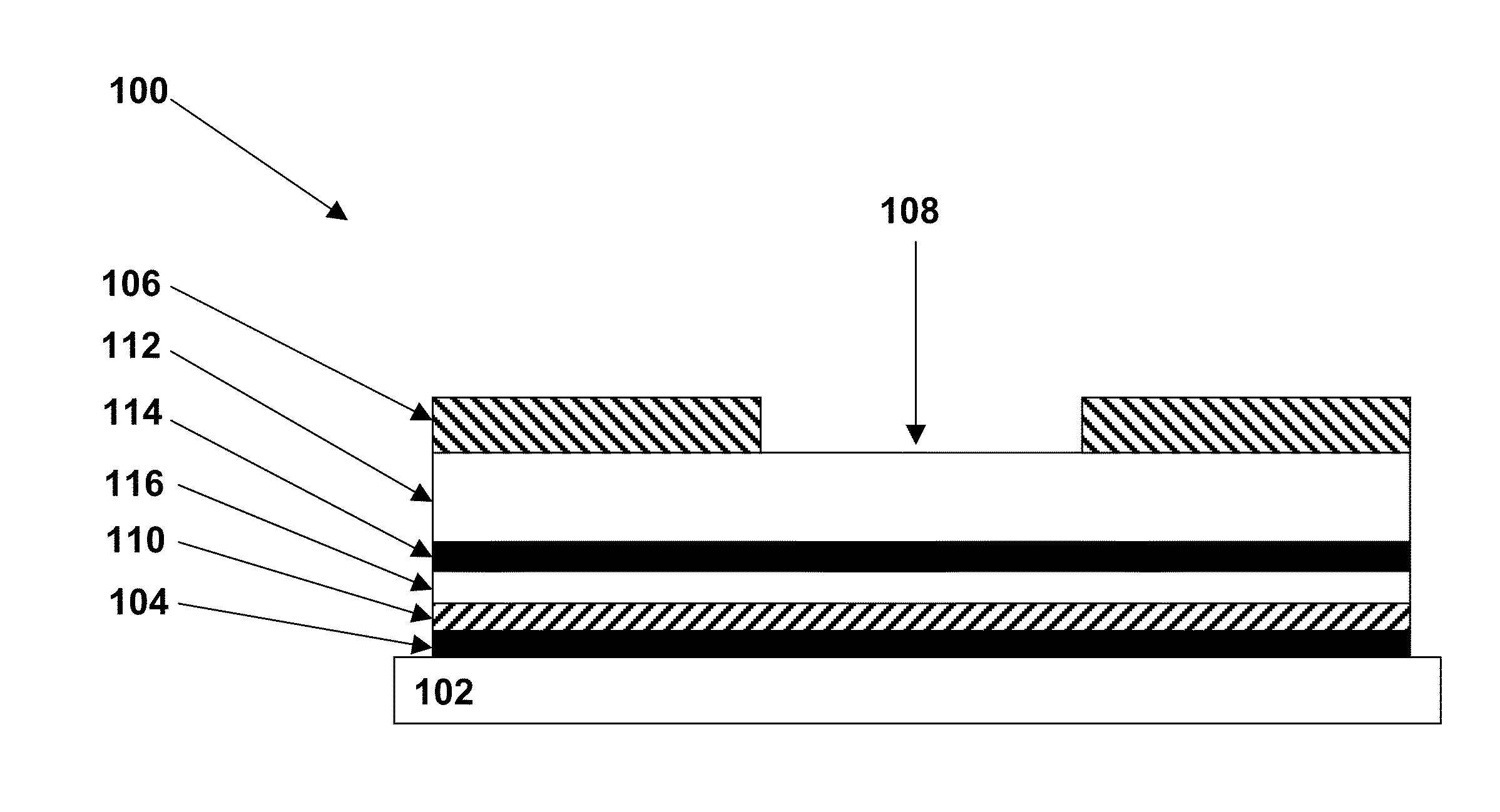
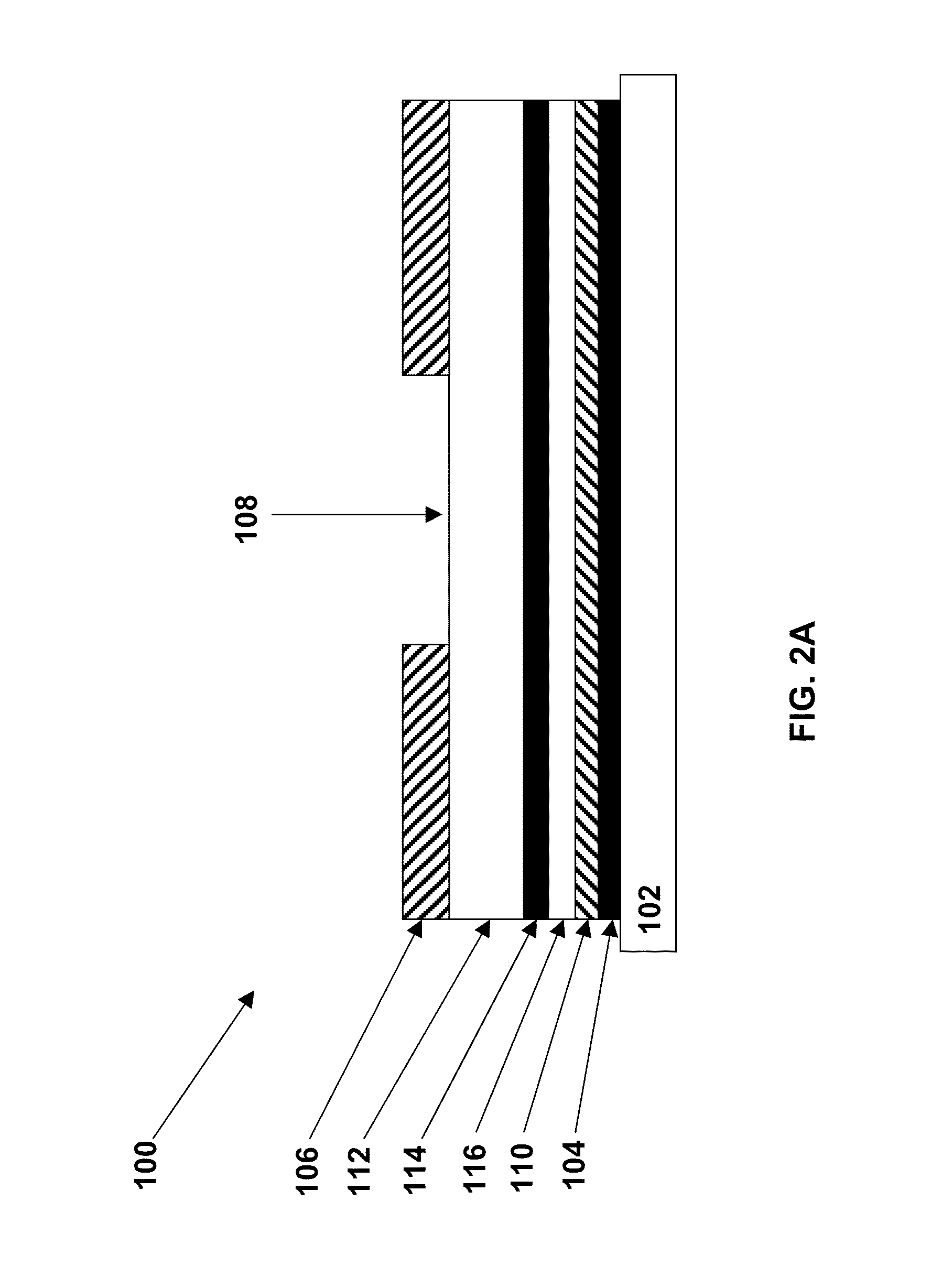
[0122]One illustrative layer of functional compositions that is disposed on an electrode within an electrode array is illustrated in FIG. 2C. The IRM is comprised of pHEMA and silane and is deposited using a spray application. A thicker layer of IRM is typically applied on the hospital sensor to reduce the response to 20 mg / dL acetaminophen. This sensor with this IRM has a 50% response to 20 mg / dL acetaminophen.

[0123]The analyte modulating layer in this sensor comprises a glucose limiting membrane (GLM). The GLM layer comprises a blended mixture of a linear polyu...

example 2

Illustrative Continuous Glucose Monitoring Algorithm

[0125]In certain embodiments of the invention, the continuous glucose monitoring (HCGM) system consists of a quad-sensor (four sensors as a set), a sensor processor and a monitor. All of the four sensors in the quad-sensor set are electrochemical sensors with three electrodes: a working electrode, a reference electrode and a counter electrode. There are two groups of sensors in the quad-sensor set. In one group, the sensors have a first “full-sized” working electrode with a first electroactive area. They are called full-size sensors (FSS). In the other group, the sensors' working electrode is half of the size of the FSS. They are called half-size sensors (HSS). In the quad-sensor set, there are two sensors in FSS group and two sensors in HSS group. Each of the four sensors will generate two signals. One is the current signal Isig, which measures the response of the sensor to the glucose level. The other is the voltage signal Vcount...

example 3

Glucose Monitoring Systems Exhibiting Enhanced Performance in the Critically Ill

[0152]The disclosure provided herein provides methods and materials for combining sensor readings to give a single output. The performance of most continuous monitoring sensors today is characterized by the mean absolute relative difference (MARD). Using this criteria, the above-noted sensor structures (in which each patient had two sensors) in combination with the algorithms designed for use with such structures were shown to exhibit surprising good properties. Specifically, the individual sensor performance was at about 16% MARD. With the algorithms disclosed herein where the sensor data is combined (by for example, determining a mean value for a signal obtained from the multiple electrode arrays; and / or determining a standard deviation for a signal obtained from the multiple electrode arrays), then assessed for performance, which showed an 11% MARD; a significant difference.

Methods:

[0153]A study was c...


PUM


Abstract

Embodiments of the invention provide amperometric analyte sensors having multiple related structural elements (e.g. sensor arrays comprising a working, counter and reference electrode) and algorithms designed for use with such sensors. While embodiments of the innovation can be used in a variety of contexts, typical embodiments of the invention include glucose sensors used in the management of diabetes.

Description

CROSS REFERENCE TO RELATED APPLICATIONS[0001]This application claims priority under Section 119(e) from U.S. Provisional Application Ser. No. 61 / 357,803, filed Jun. 23, 2010; and U.S. Provisional Application Ser. No. 61 / 385,418 filed Sep. 22, 2010; and claims priority under Section 120 from U.S. application Ser. No. 12 / 914,969, filed Oct. 28, 2010, the contents of each of which are incorporated herein by reference. This application is related to U.S. patent application Ser. No. 12 / 572,087, U.S. patent application Ser. No. 11 / 897,106 and U.S. patent application Ser. No. 12 / 643,790, the contents of each of which are herein incorporated by reference.BACKGROUND OF THE INVENTION[0002]1. Field of the Invention[0003]Analyte sensor systems (e.g. glucose sensor systems used in the management of diabetes) and methods and materials for making and using such sensor systems.[0004]2. Description of Related Art[0005]Analyte sensors such as biosensors include devices that use biological elements to...

Claims


Application Information

Patent Timeline
IPC IPC(8): A61B5/145
CPCA61B5/0017A61B5/14503A61B5/14532G01N27/307A61B5/726C12Q1/001A61B5/1486
Inventor GOTTLIEB, REBECCA K.CHIU, CHIA-HUNGRAMACHANDRAN, MEENADANGUI-PATEL, NANDITAROSE, JEFFERSONRAO, ASHWIN K.WANG, HSIFULUO, YING
Owner MEDTRONIC MIMIMED INC
Learn More