Inertially Tracked Objects

a tracking system and object technology, applied in the field of computer-based methods and apparatuses, can solve the problems of often more expensive optical tracking systems than inertial tracking systems, and achieve the effects of avoiding disadvantages, avoiding drift, and cost-effectiveness

Active Publication Date: 2011-12-29
MAKO SURGICAL CORP
View PDF3 Cites 85 Cited by
  • Summary
  • Abstract
  • Description
  • Claims
  • Application Information

AI Technical Summary

Benefits of technology

[0008]The techniques described herein provide surgical systems and methods for inertially tracking objects and eliminating drift associated with the tracked objects by resetting the reference pose of the inertial tracker(s) mounted to the tracked objects. A reproducible reference pose is established between the tracked objects such that the tracked objects can be repeatedly and accurately placed into the reproducible reference pose to reset a tracking calculation between the objects. When the drift associated with an inertial tracker mounted to one (o...

Problems solved by technology

For example, optical tracking systems are often more expensive than inertial tracking systems and the s...

Method used


Image

  • Inertially Tracked Objects
  • Inertially Tracked Objects
  • Inertially Tracked Objects

Examples


Embodiment Construction

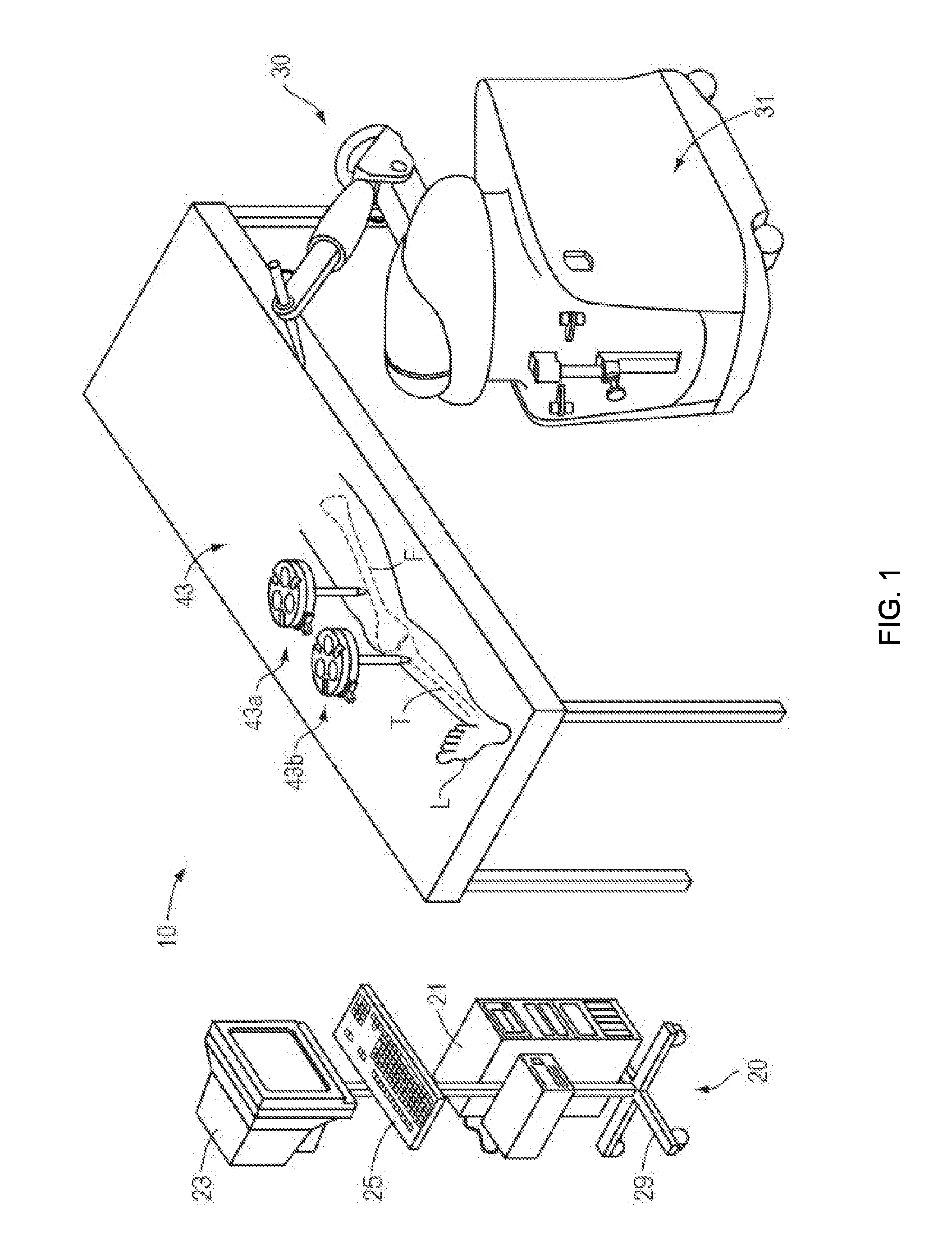
[0034]Presently preferred embodiments of the invention are illustrated in the drawings. Although this specification refers primarily to object tracking during image-guided orthopedic surgical procedures involving the knee joint, it should be understood that the subject matter described herein is applicable to other types of navigated surgical procedures, including imageless surgical procedures, as well as to non-surgical applications involving object tracking

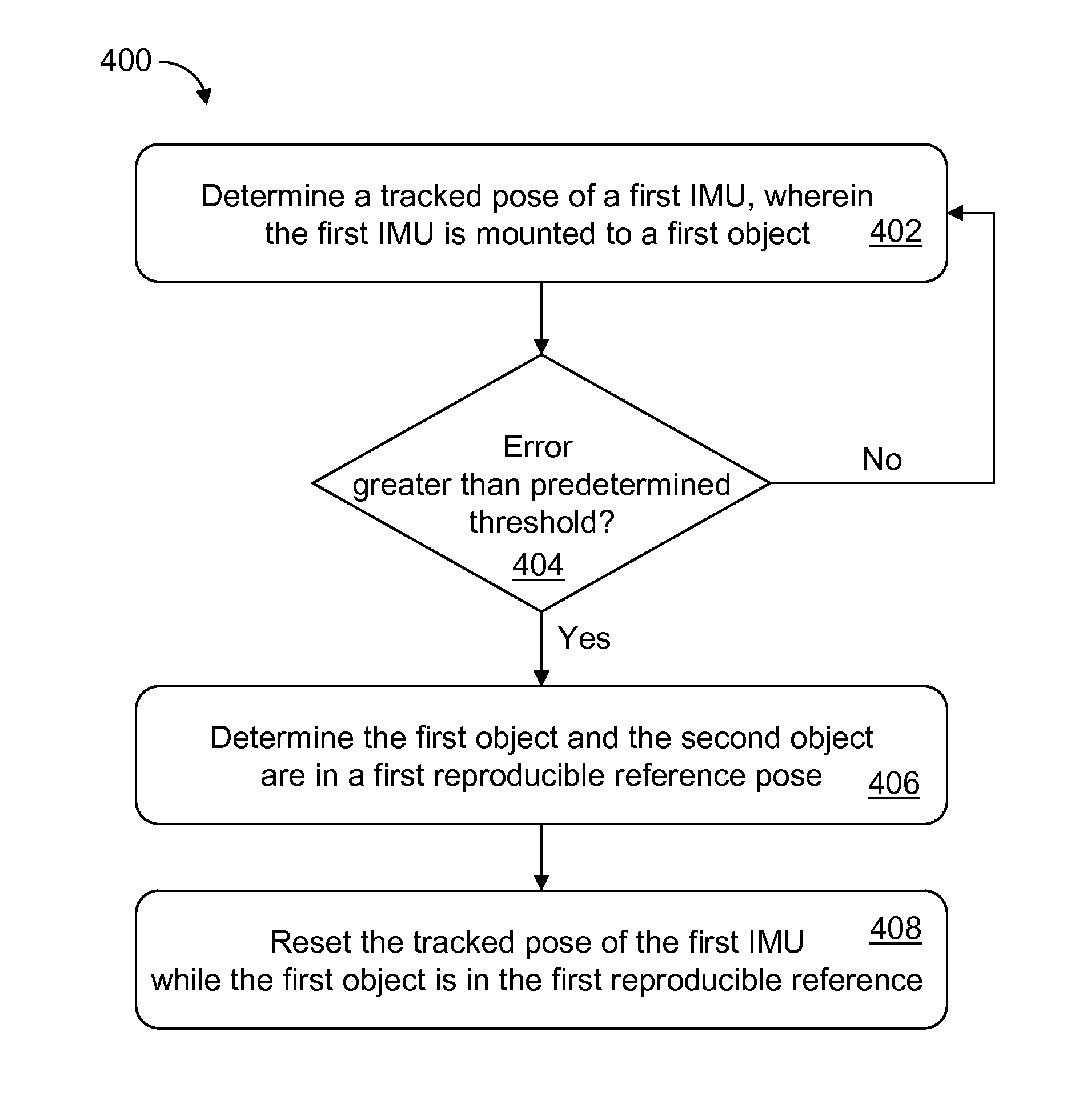
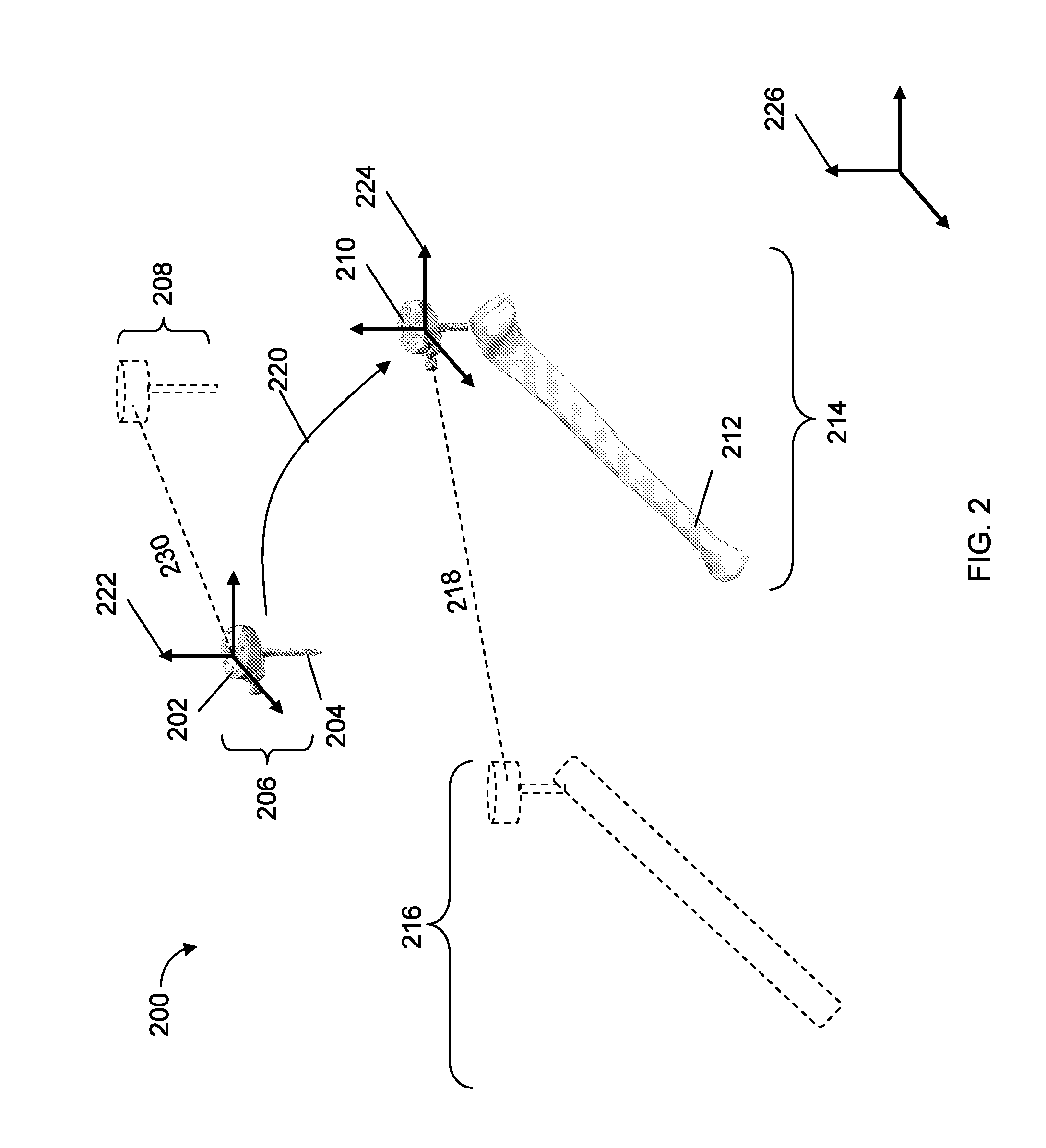
[0035]According to the present invention, a reference position for an inertial tracking element or tracker (e.g., for an IMU) can be reset based on a reproducible reference pose to eliminate an error (e.g., drift) associated with the inertial tracker. The reproducible reference pose can be achieved by kinematically coupling the inertial tracker to a second object, such as a second inertial tracker or an untracked coupling element. The inertial tracking system can subsequently track the inertial tracker based on the reset referen...


PUM


Abstract

Described are computer-based methods and apparatuses, including computer program products, for inertially tracked objects with a kinematic coupling. A tracked pose of a first inertial measurement unit (IMU) is determined, wherein the first IMU is mounted to a first object. The tracked pose of the first IMU is reset while the first object is in a first reproducible reference pose with a second object.

Description

FIELD OF THE INVENTION[0001]The present invention relates generally to computer-based methods and apparatuses, including computer program products, for inertially tracked objects.BACKGROUND[0002]Orthopedic joint replacement surgery may involve arthroplasty of a knee, hip, or other joint (e.g., shoulder, elbow, wrist, ankle, finger, etc.). During joint replacement surgery, a surgeon typically removes diseased bone from the joint and replaces the resected bone with prosthetic implant components. Challenges of joint replacement surgery include determining the appropriate position for implant components within the joint relative to the bone and other implant components and accurately cutting and reshaping bone to precisely correspond to the planned placement of the implant components. Inaccurate positioning of implants may compromise joint performance and reduce implant life.[0003]A surgical system for joint replacement surgery can include a haptic device configured to be manipulated by...

Claims


Application Information

Patent Timeline
IPC IPC(8): G06F19/00G01P21/00
CPCA61B19/5244A61B2017/00477A61B2017/00725A61B2017/00876A61B2019/527A61B2019/5248A61B2019/5259A61B2019/5268A61B2019/4894A61B2090/0818A61B2034/2048A61B2034/2068A61B2034/207A61B2034/2059A61B34/20G01C21/166
Inventor LIGHTCAP, CHRISKANG, HYOSIG
Owner MAKO SURGICAL CORP
Why Eureka
Try Eureka