
Multi-unit Modular Stackable Switched Reluctance Motor System with Parallely Excited Low Reluctance Circumferential Magnetic Flux loops for High Torque Density Generation

a switched reluctance, high torque density technology, applied in the direction of dynamo-electric machines, instruments, clocks, etc., can solve the problems of complex drive electronics, and achieve the effects of high torque density, low cost, and high robustness and reliability

Inactive Publication Date: 2012-01-05
LUSTONE TECH
View PDF31 Cites 31 Cited by
  • Summary
  • Abstract
  • Description
  • Claims
  • Application Information

AI Technical Summary

Benefits of technology

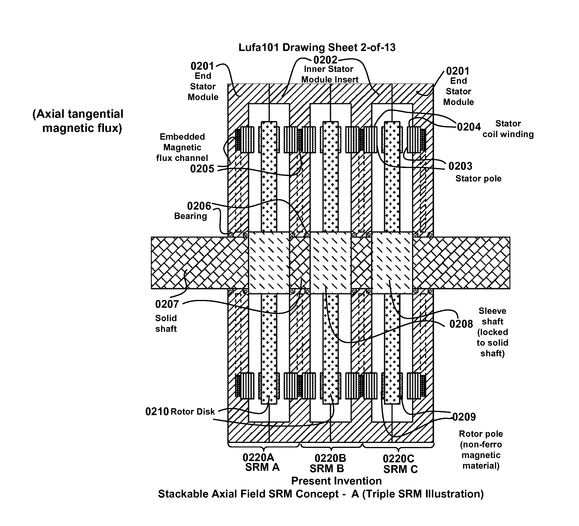
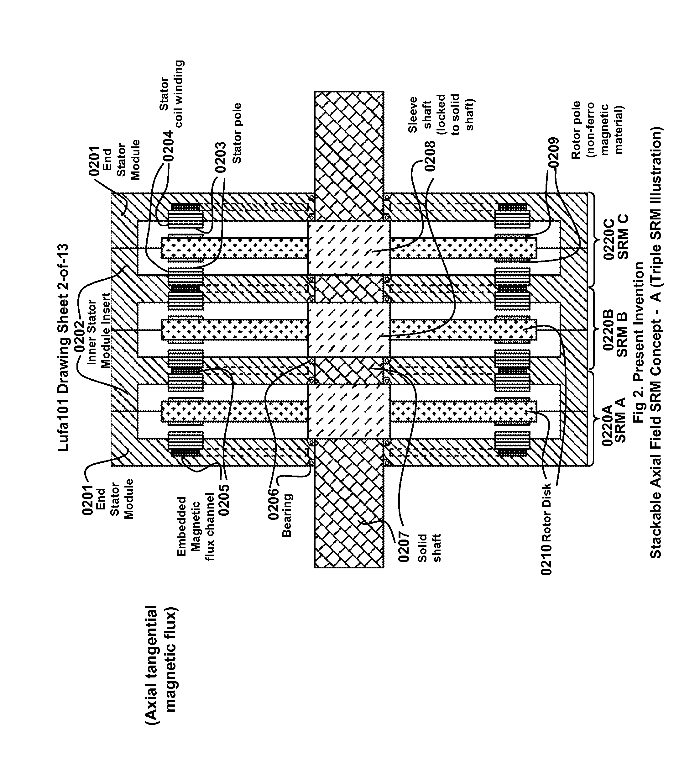
[0007]Under a variety of embodiments, the present invention is a multi-unit modular stackable motor system (MUMMS) apparatus to generate rotation with high torque density in controllable speed and controllable torque and it has advantages including mechanical simplicity (the simplest amongst all electric motors), low cost, high robustness and reliability, superior torque and power outputs per unit volume or per unit mass (torque density). These good attributes are due to the absence of armature winding, permanent magnets and commutated brushes in the rotor. The SRM can offer high level of performance, such as torque and power, over a range of rotation speeds. However, the drive electronics could be complex when operation employs multiphase excitation of stator groups. For broad applications, cost on the essential electronic components needs to be sufficiently reasonable. The MUMMS includes a rotor shaft with a shaft core with a first shaft end and a second shaft end and an N-module motor system (NMMS) having a set of multiple independent SRM modules stacked together, i.e., stacked switched reluctance motor modules (SSRMj where j>=1) are locked to the rotor shaft along the rotor shaft and coaxially coupled to the rotor shaft using the rotor shaft as its rotation center axis and producing a total output torque that is the sum total of those produced by each SSRMj. More precisely expressed in a composite Cartesian and polar coordinate system r-θ-Z, the MUMMS rotational plane is in parallel to the X-Y plane and the r-θ plane.
[0010]In another more specific embodiment, each RPSj has a set of circumferential rotor pole elements (CRPEjk, k=1,2, . . . , P where P>1) located near the RDUj periphery and further distributed along θ-direction according to a first set of pre-determined θ-coordinates. Correspondingly, each SPSj has a set of circumferential stator pole elements (CSPEjm, m=1,2, . . . , Q where Q>1) located near the RDUj periphery, further distributed along θ-direction according to a second set of pre-determined θ-coordinates and each CSPEjm has a stator pole coil set (SPCSjm) having stator coil interconnecting terminals (SCITjm) and wound upon said CSPEjm upon powering of each SPCSjm with a stator coil current (SCCjm) via the SCITjm with a phase according to the relative θ-coordinate between the RDUj and its two neighboring stator units. Corresponding to each CRPEjk a local, short-path thus low reluctance circumferential magnetic flux field (CMFFjk) with low magnetic loss can be successfully excited by the powered SPCSjm while said each CRPEjk passing through each of the CSPEjm thus producing a high component switched reluctance torque (SRTQjk). And the SSRMj produces a switched reluctance torque (SRTQj) equal to SRTQj1+SRTQj2+ . . . +SRTQjP.
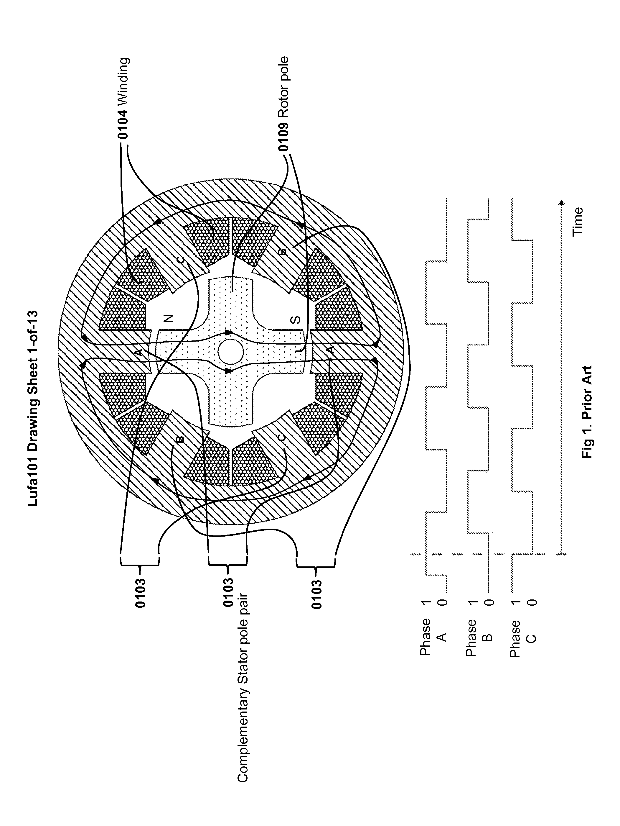
[0028]High performance from SRM is obtainable only via sophisticated control electronics that help compensate the non-linear behavior between the drive current (supplied to the stator coil) and the output torque. The nonlinearity is due to the intrinsic nature of changing reluctance when the rotor is moving into and out of the stator field. The availability of control electronics at reasonable cost will be key for SRM to gain broader foothold in motor drive applications.

Problems solved by technology

However, the drive electronics could be complex when operation employs multiphase excitation of stator groups.

Method used


Image

  • Multi-unit Modular Stackable Switched Reluctance Motor System with Parallely Excited Low Reluctance Circumferential Magnetic Flux loops for High Torque Density Generation
  • Multi-unit Modular Stackable Switched Reluctance Motor System with Parallely Excited Low Reluctance Circumferential Magnetic Flux loops for High Torque Density Generation
  • Multi-unit Modular Stackable Switched Reluctance Motor System with Parallely Excited Low Reluctance Circumferential Magnetic Flux loops for High Torque Density Generation

Examples


Embodiment Construction

[0046]The description above and below plus the drawings contained herein merely focus on one or more currently preferred embodiments of the present invention and also describe some exemplary optional features and / or alternative embodiments. The description and drawings are presented for the purpose of illustration and, as such, are not limitations of the present invention. Thus, those of ordinary skill in the art would readily recognize variations, modifications, and alternatives. Such variations, modifications and alternatives should be understood to be also within the scope of the present invention.

[0047]For a first purpose of achieving high rotation torque density of a motor, the present invention provides a motor apparatus that is capable of shortening the paths of magnetic flux, extending the drive arm, and reducing the mass / volume of a rotor. For a second purpose of lowering the overall cost, the present invention provides a motor apparatus that is capable of minimizing use of...


PUM


Abstract

The present invention is a apparatus of multi-unit modular stackable switched reluctance motor system with parallely excited low reluctance circumferential magnetic flux loops for high torque density generation. For maximized benefits and advanced motor features, the present invention takes full combined advantages of both SRM architecture and “Axial Flux” architecture by applying “Axial Flux” architecture into SRM design without using any permanent magnet, by modularizing and stacking the “Axial Flux” SRM design for easy configuration and customization to satisfy various drive torque requirements and broad applications, and by incorporating an en energy recovery transformer for minimizing switching circuitry thus further lowering the cost and further increasing the reliability and robustness. Unlike prior arts, the present invention does not use any permanent magnet and this “Axial Flux” SRM system is modularized and stackable with many benefits.

Description

CROSS REFERENCE TO RELATED APPLICATIONS[0001]This application is based upon and claims the priority of a previously filed provisional patent application entitled “A Modular Multi-cell Stackable Switched Reluctance Motor with Parallely Excited Low Reluctance Circumferential Magnetic Flux loops for High Torque Density Generation” by Lee et al with application No. 61 / 360,681, filing date Jul. 1, 2010 and attorney docket number Lufa100 whose content is herein incorporated by reference for all purposes.FIELD OF INVENTION[0002]The present invention relates generally to the field of switched reluctance motors constructions. More specifically, the present invention is directed to techniques and associated motor designs capable of generating high torque density with simplicity and low cost.BACKGROUND OF THE INVENTION[0003]The switched reluctance motors (SRM), for variable speed and torque applications, have many advantages including mechanical simplicity (the simplest amongst all electric mo...

Claims


Application Information

Patent Timeline
IPC IPC(8): H02K37/08
CPCH02K16/00H02K2213/12H02K2201/12H02K19/103
Inventor LEE, YEE-CHUNYANG, CHUNG CHING
Owner LUSTONE TECH
Learn More