Magnetic modue of electron cyclotron resonance and electron cyclotron resonance apparatus using the same

a technology of electron cyclotron and magnetic modue, which is applied in the field of plasma generation technique, can solve the problems of requiring a large amount of cooling water for heat dissipation, and achieve the effect of consuming less power wattage and operating smoothly

Inactive Publication Date: 2012-01-05
IND TECH RES INST
View PDF12 Cites 4 Cited by
  • Summary
  • Abstract
  • Description
  • Claims
  • Application Information

AI Technical Summary

Benefits of technology

[0006]The present disclosure provides a magnetic module for electron cyclotron resonance (ECR) and ECR apparatus using the same, in which the magnetic module uses permanent magnets as its magnetic field source, and a microwave force for producing an electric field, that are operated in a low pressure environment of 9×10⁻⁵ torr, so as to induce electron cyclotron resonance in a magnetic field of 875 gauss and an electric filed of 2.45 GHz and 70 W. Thereby, the magnetic module is enabled to operate smoothly without the need of any additional current or cooling water as the conventional ECR devices, and also is capable of being used for depositing a film of signal atom layer while consuming less power wattage under low pressure environment.

Problems solved by technology

Moreover, since conventionally the electron cyclotron resonance chemical vapor deposition (ECR-CVD) tool is configured as an electromagnetic system, it is a high current application that requires a great amount of cooling water for heat dissipation.

Method used


Image

  • Magnetic modue of electron cyclotron resonance and electron cyclotron resonance apparatus using the same
  • Magnetic modue of electron cyclotron resonance and electron cyclotron resonance apparatus using the same
  • Magnetic modue of electron cyclotron resonance and electron cyclotron resonance apparatus using the same

Examples


Embodiment Construction

[0022]For your esteemed members of reviewing committee to further understand and recognize the fulfilled functions and structural characteristics of the disclosure, several exemplary embodiments cooperating with detailed description are presented as the follows.

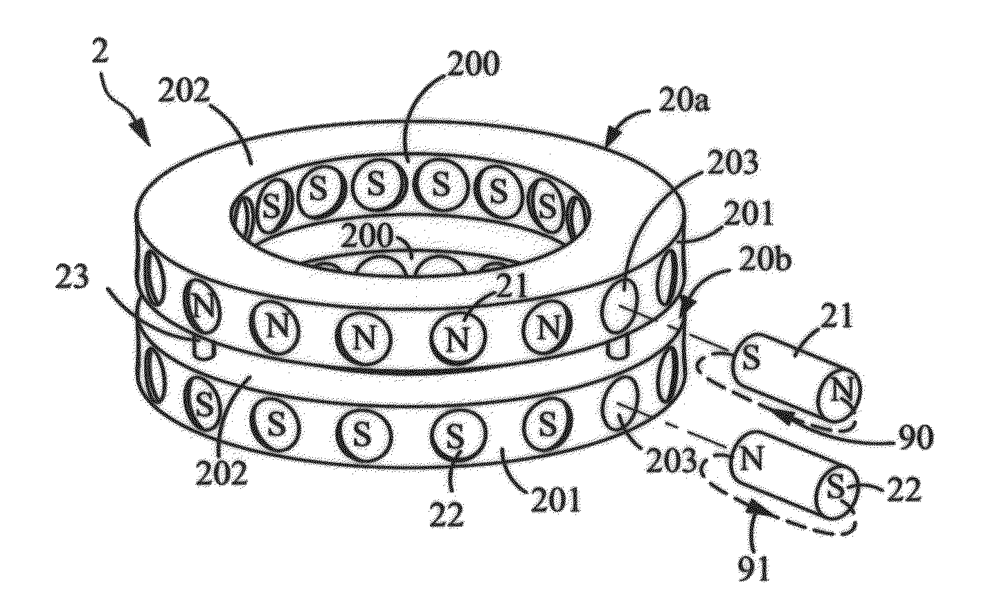
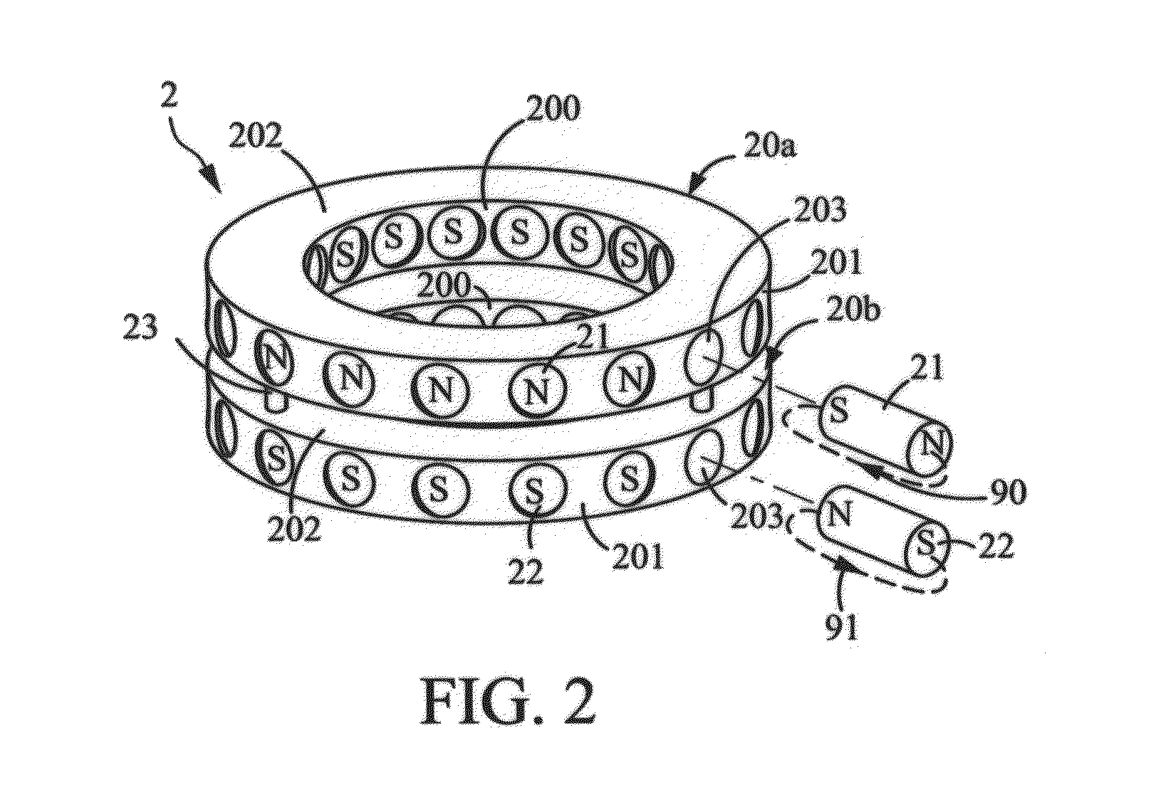
[0023]Please refer to FIG. 2, which is a three-dimensional view of a magnetic module for electron cyclotron resonance according to a first embodiment of the present disclosure. In this embodiment, the magnetic module 2 includes two supporting rings 20a, 20b and a plurality of magnetic pillars, as the two magnetic pillars 21, 22 illustrated in FIG. 2, in which the two supporting rings 20a, 20b are coaxially arranged and vertically stacked. Since the two supporting rings 20a, 20b are structurally the same, the following description only addresses the supporting ring 20a as illustration. As shown in FIG. 2, the supporting ring 20a is configured with an inner surface 200 and an outer surface 201 that are connected with each other...


PUM


Abstract

The present invention provides a magnetic module for electron cyclotron resonance (ECR) and ECR apparatus using the magnetic module, wherein the magnetic module comprises a plurality of layers of supporting ring and a plurality of magnetic pillars. Each of the supporting rings has an outer surface and an inner surface and has a plurality of through holes radially disposed inside the supporting ring. The plurality of pillars are respectively embedded into the plurality of through holes of each supporting ring and magnetic fields of the magnetic pillars in each two adjacent supporting ring are respectively opposite to each other. The ECR apparatus of the present invention is capable of being operated under lower pressure environment for forming a single atom layer on a substrate.

Description

CROSS-REFERENCE TO RELATED APPLICATIONS[0001]This non-provisional application claims priority under 35 U.S.C. §119(a) on Patent Application No(s). 099121856 filed in Taiwan, R.O.C. on Jul. 2, 2010, the entire contents of which are hereby incorporated by reference.TECHNICAL FIELD[0002]The present disclosure relates to a plasma generation technique, and more particularly, to a magnetic module for electron cyclotron resonance (ECR) and ECR apparatus using the same, capable of operating under lower pressure environment for generating high-density plasma.TECHNICAL BACKGROUND[0003]As semiconductor components being made thinner, lighter and smaller, current chemical vapor (CVD) process is able to deposit a film of single atom layer. However, in order to obtain a satisfactory single atom layer, a high density plasma deposition equipment for performing under a low-pressure environment is required. Moreover, since conventionally the electron cyclotron resonance chemical vapor deposition (ECR-...

Claims


Application Information

Patent Timeline
Patent Type & Authority Applications(United States)
IPC IPC(8): H01J7/00
CPCH01J37/32678
Inventor CHANG, CHIH-CHENHUANG, KUN-PINGLEE, KANG-FENG
Owner IND TECH RES INST
Why Eureka
Try Eureka