Numerical controller for multi-axis machine

a multi-axis machine and controller technology, applied in the direction of electric programme control, program control, instruments, etc., can solve the problems of insufficient error-free compensation of the tool center point position to an error-free position, inability to achieve high-precision machining, and erroneous tool posture (orientation)

Active Publication Date: 2012-01-05
FANUC LTD
View PDF17 Cites 24 Cited by
  • Summary
  • Abstract
  • Description
  • Claims
  • Application Information

AI Technical Summary

Benefits of technology

[0025]According to the present invention, the error amounts are set in association with respective errors, the translation compensation amount is obtained from the error amounts and added to the command linear axis position, and the rotation compensation amount is also obtained as the rotary axis compensation amount and added to the command rotary axis position. Thereupon, the tool center point can be moved to the error-free position, and the tool posture can also be compensated in an error-free direction to ensure high-precision machining. This high-precision machining can be performed by means of multi-axis machines of a tool-head-rotation type, mixed two-axis table type, mixed two-axis tool head type, and table rotation type.

Problems solved by technology

Thus, although the tool center point is moved to the error-free position, the tool posture (orientation) remains erroneous.
However, if a side face of a tool is used for machining or in the case of boring in which machining is directed toward the tool, the tool posture (orientation) is an important factor, and simple compensation of the tool center point position to an error-free position is not enough.
Thus, according to the prior art disclosed in the above patent document, high-precision machining cannot be achieved if there is any error attributable to a machine system during the boring or machining with the side face of the tool.
However, the main errors derive from a moving body.
Therefore, an error in the rotary tool head depends on the position of a rotary axis about which the tool head is rotated and that of a linear axis on which the tool head lies.
On the other hand, an error in the rotary table depends on the position of a rotary axis about which the table is rotated and that of a linear axis on which the table lies.

Method used


Image

  • Numerical controller for multi-axis machine
  • Numerical controller for multi-axis machine
  • Numerical controller for multi-axis machine

Examples


Embodiment Construction

[0049]The present invention is intended to provide a multi-axis machine comprising at least three linear axes and three rotary axes.

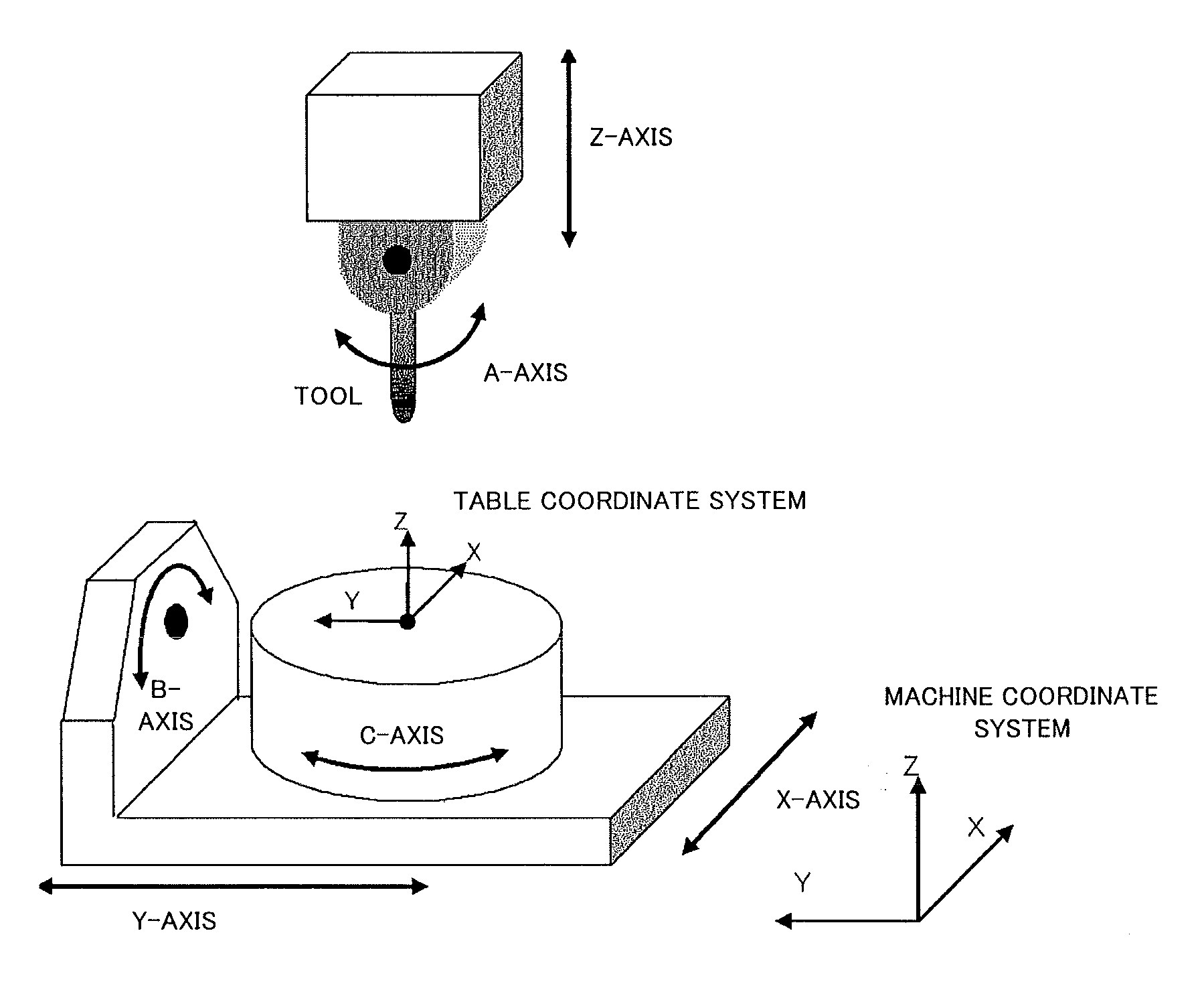
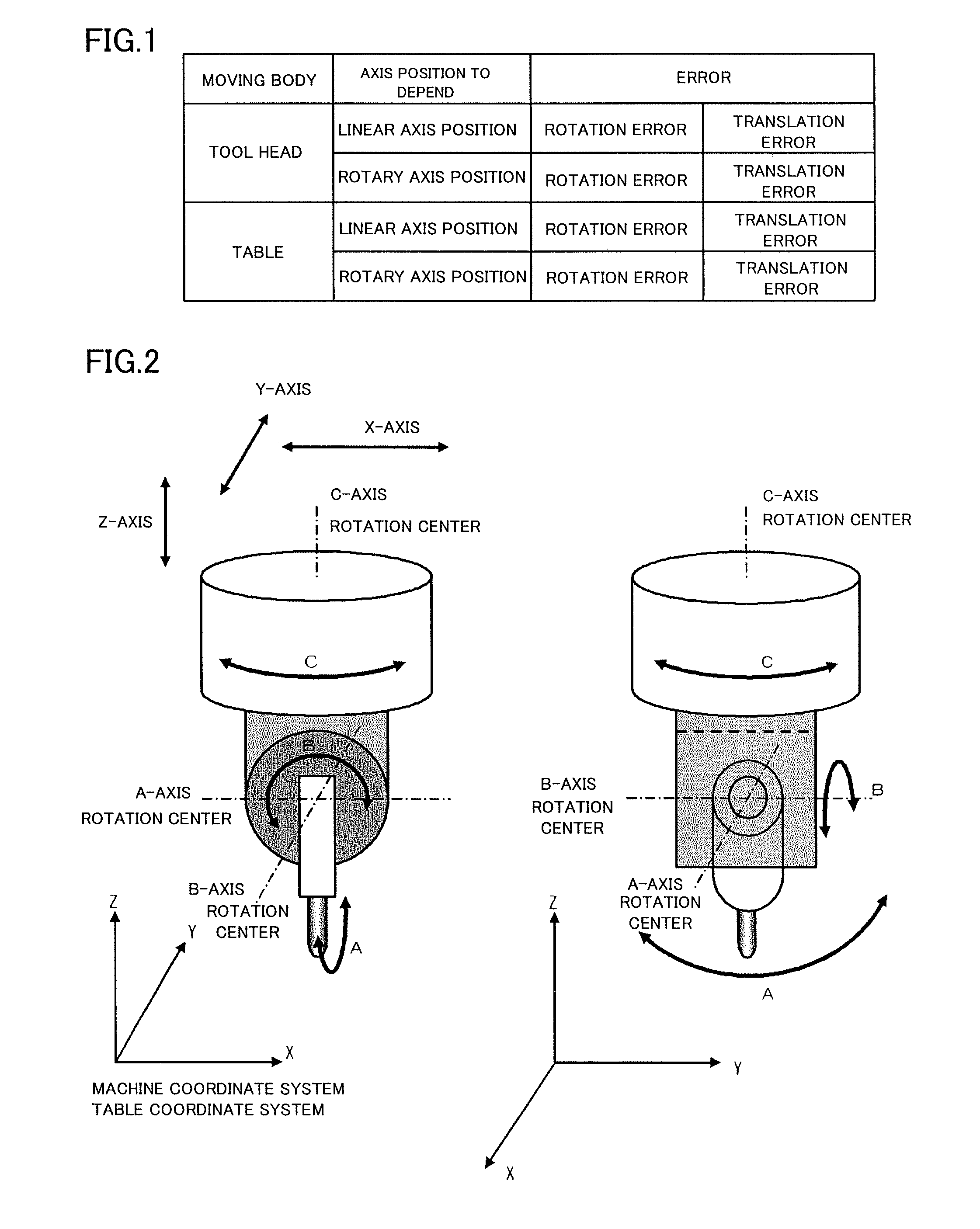
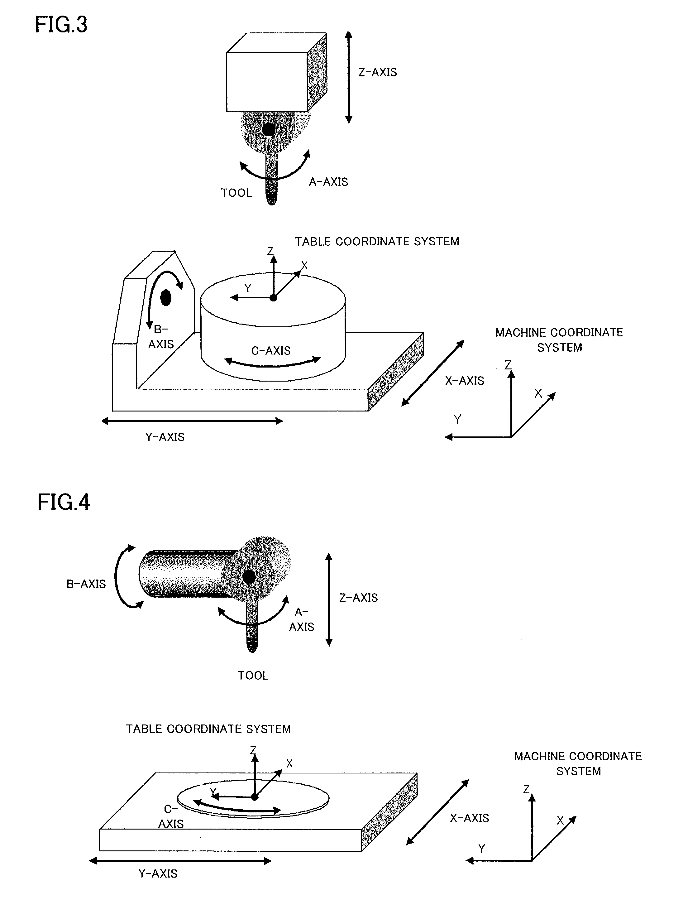
[0050]FIGS. 2 to 5 show examples of the multi-axis machine controlled by a numerical controller according to the present invention. The example shown in FIG. 2 is a tool-head-rotation type in which a tool head is rotated about three rotary axes. The example shown in FIG. 3 is a mixed two-axis table type (in which a table is rotated about two rotary axes and a tool head is rotated about a single axis). The example shown in FIG. 4 is a mixed two-axis tool head type (in which a tool head is rotated about two rotary axes and a table is rotated about a single rotary axis). The example shown in FIG. 5 is a table-rotation type in which a table is rotated about three axes.

[0051]The basic function of the numerical controller according to the present invention will be described first. FIG. 6 is a diagram showing a multi-axis machine in which a tool head and a tab...


PUM


Abstract

A numerical controller for controlling a multi-axis machine calculates an axis-dependent translation error amount and an axis-dependent rotation error amount based on a command axis position. Translation and rotation compensation amounts are calculated based on the axis dependent translation and rotation error amounts, respectively. The translation and rotation compensation amounts are added to command linear and rotary axis positions, respectively. Three linear axes and three rotary axes are driven to the added positions, individually. Thus, there is provided a numerical controller that enables even machining with a side face of a tool or boring to be in commanded tool position and posture (orientation) in the multi-axis machine.

Description

BACKGROUND OF THE INVENTION[0001]1. Field of the Invention[0002]The present invention relates to a numerical controller for controlling a multi-axis machine having at least three linear axes and three rotary axes. More particularly, the invention relates to a numerical controller configured to perform compensations corresponding to table linear-axis translation and rotation errors dependent on a linear axis position for table drive, table rotary-axis translation and rotation errors dependent on a rotary axis position for table drive, tool head linear-axis translation and rotation errors dependent on a linear axis position for tool head drive, and tool head rotary-axis translation and rotation errors dependent on a rotary axis position for tool head drive, thereby moving a tool center point to an error-free position and moving the tool posture (orientation) to an error-free tool posture and ensures control for high-precision machining.[0003]2. Description of the Related Art[0004]Japa...

Claims


Application Information

Patent Timeline
Patent Type & Authority Applications(United States)
IPC IPC(8): G05B19/404
CPCG05B19/404G05B2219/49198G05B2219/50297
Inventor OTSUKI, TOSHIAKIIDE, SOICHIROHANAOKA, OSAMUSASAKI, TAKAFUMI
Owner FANUC LTD
Why Eureka
Try Eureka