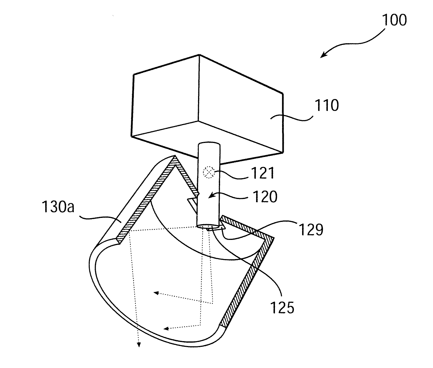
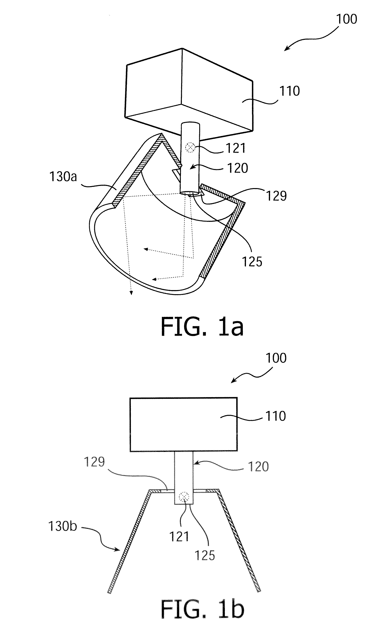
[0007]Thus, a light emitting device is provided having a movably arranged collimating unit which encompasses a light output portion arranged on the light output unit. Substantially all light outputted from the light output portion is thus directly injected into the collimating unit, thereby allowing a high light output yield. The collimating unit collimates the light, and depending on the desired
light beam direction, the movably arranged collimating unit is adjusted accordingly. Meanwhile, the position of the light output portion is kept fixed. With the present inventive concept a high flexibility of the angle of the
light beam direction is provided. The collimating unit may be arranged such that the light rays outputted at the light output portion hits the
collimator a limited amount of times, preferably 0 or 1 times. The invention further provides a simple
mechanical construction, which provides a compact, light and cheap solution for the adjustment of the direction of the outputted light from the light emitting device. In addition, no housing is required to seal the light emitting device. Additionally having the cooling means on a set position or orientation can be advantageous because the cooling can be made more effective as the air flows around the device will always be oriented in the same direction. The at least one
light source may be one of a
light emitting diode, a
laser, a CDM and an incandescent.
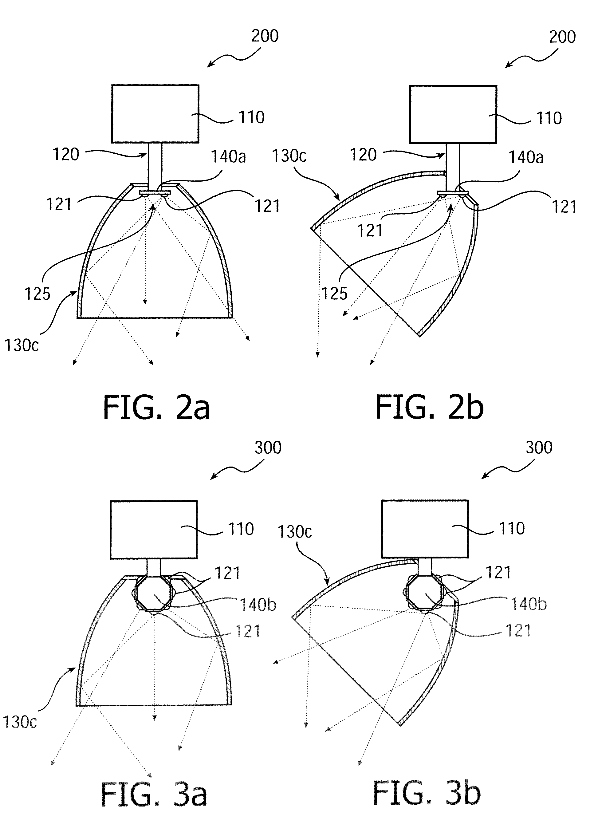
[0009]In accordance with an embodiment of the light emitting device, the collimating unit is arranged to be tiltable with respect to the light output unit and the base unit. Furthermore, the combination of the collimating unit, the base unit, and the light output unit is arranged to be rotatable. This allows for the light output portion to be rotated around a
vertical axis with respect to the combination, while still having the same position within the movably arranged
collimator. Having the base unit arranged to be rotatable around a
vertical axis is advantageous because only the tilt mechanism between the base unit and the light output unit is then required. Depending on the arrangement of the light output portion, the rotation around the
vertical axis may, in addition to the collimation of the collimating unit, slightly influence the appearance of the final outputted light distribution, and / or set the
light beam direction.
[0012]In accordance with an embodiment of the light emitting device, the light output unit further comprises a mixing rod having a first end arranged at the at least one
light source, and a second end forming the light output portion. With this arrangement, the light sources may be arranged directly onto a
heat sink, thus increasing the efficiency of the cooling of the light sources. Also, because the light output portion is kept separated from the light sources, the risk for a user to burn himself on the light emitting device is decreased, as the light output is separated from the heat sources (light sources). The light mixing rod is further advantageous when employing light sources which emits a plurality of colors or when a smoothened light output profile is desired
[0013]In accordance with an embodiment of the light emitting device, the second end is arranged to be one of cone shaped,
pyramid shaped, and facetted. Thus, light from the light output surface may leave the light mixing rod from its vertical sides, and not just from a flat end
facet. This provides a broadening of the
light intensity distribution from the light output surface, which highly increases the amount of light that hits the inner surface of the collimating unit, i.e. less light exits the light emitting device directly without hitting the collimating unit. As a consequence, the length of the collimating unit may be decreased.
[0018]In accordance with an embodiment of the light emitting device, the light emitting device further comprises a reflector arranged at the base unit. This is advantageous for reflecting
stray light through the aperture of the collimating unit and for improving the appearance of the lamp / luminaire.
[0021]In accordance with an embodiment of the light emitting device, the base unit of is arranged to be shifted during movement of the collimating unit for adjusting the direction of the emitted light. The shifting of the position of the base unit is made in order to counterbalance a shifting of an area of the collimating unit from which the light exits the device. This area is referred to the light exit area, and is typically defined by an outer rim of the collimating unit If the collimating unit is moved to adjust the direction of the emitted light, for instance by means of tilting the collimating unit, the shifting of the light exit area of the collimating unit may be counterbalanced by simultaneously shifting the base with reference to the collimating unit, such that the total amplitude of the shifting of the exit area during adjustment of the direction of the light is decreased or totally counterbalanced. The direction of the outputted light may then be altered while still having a
fixed position of the origin of the light output. This is also advantageous when optionally arranging the light emitting device in a recess in e.g. a ceiling. As the shifting of the light exit area is decreased, the recess may be decreased and the light emitting device may be better recessed in the surface.

