Tension apparatus for patterning slit sheet

US20120006259A1Inactive Publication Date: 2012-01-12SAMSUNG DISPLAY CO LTD

Image

  • Tension apparatus for patterning slit sheet
  • Tension apparatus for patterning slit sheet
  • Tension apparatus for patterning slit sheet

Examples


Embodiment Construction

[0034]Reference will now be made in detail to the present embodiments of the present invention, examples of which are illustrated in the accompanying drawings, wherein like reference numerals refer to the like elements throughout. The embodiments are described below in order to explain the present invention by referring to the figures.

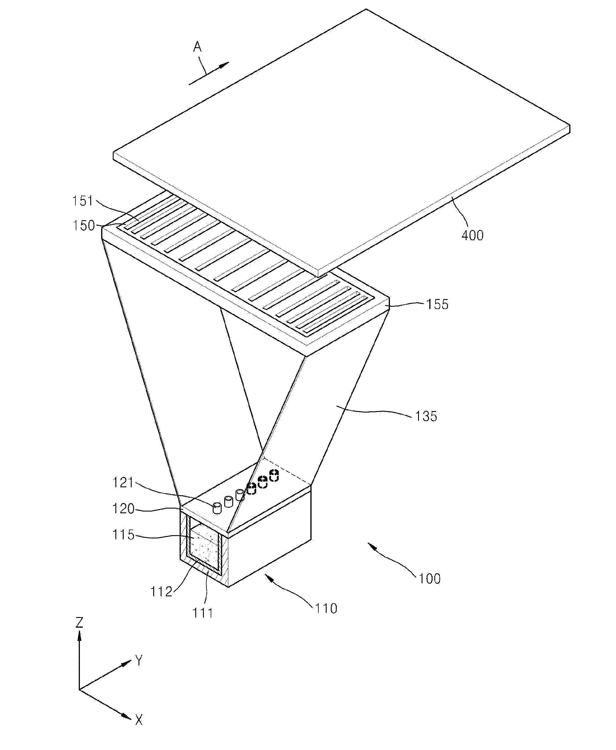
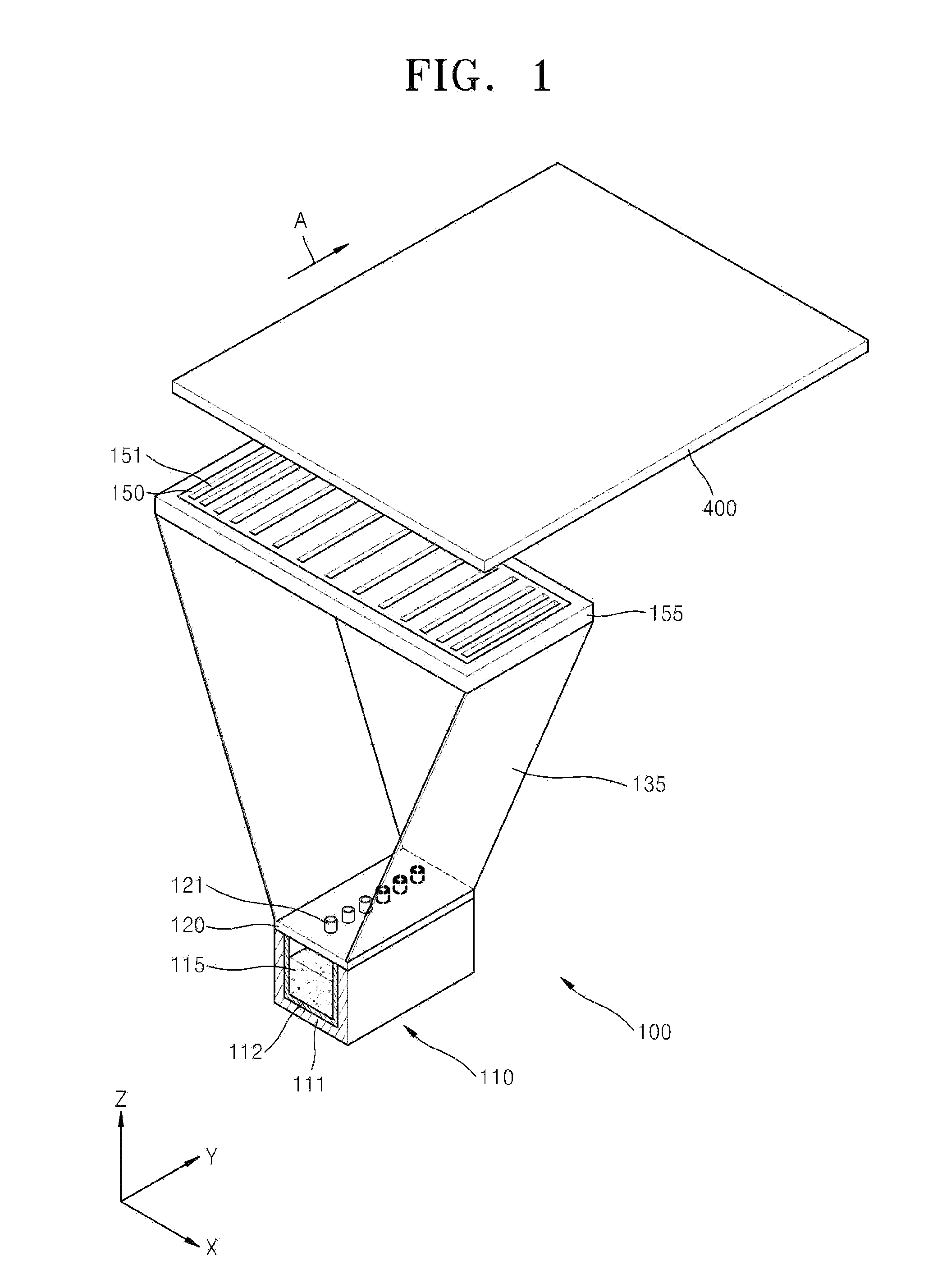
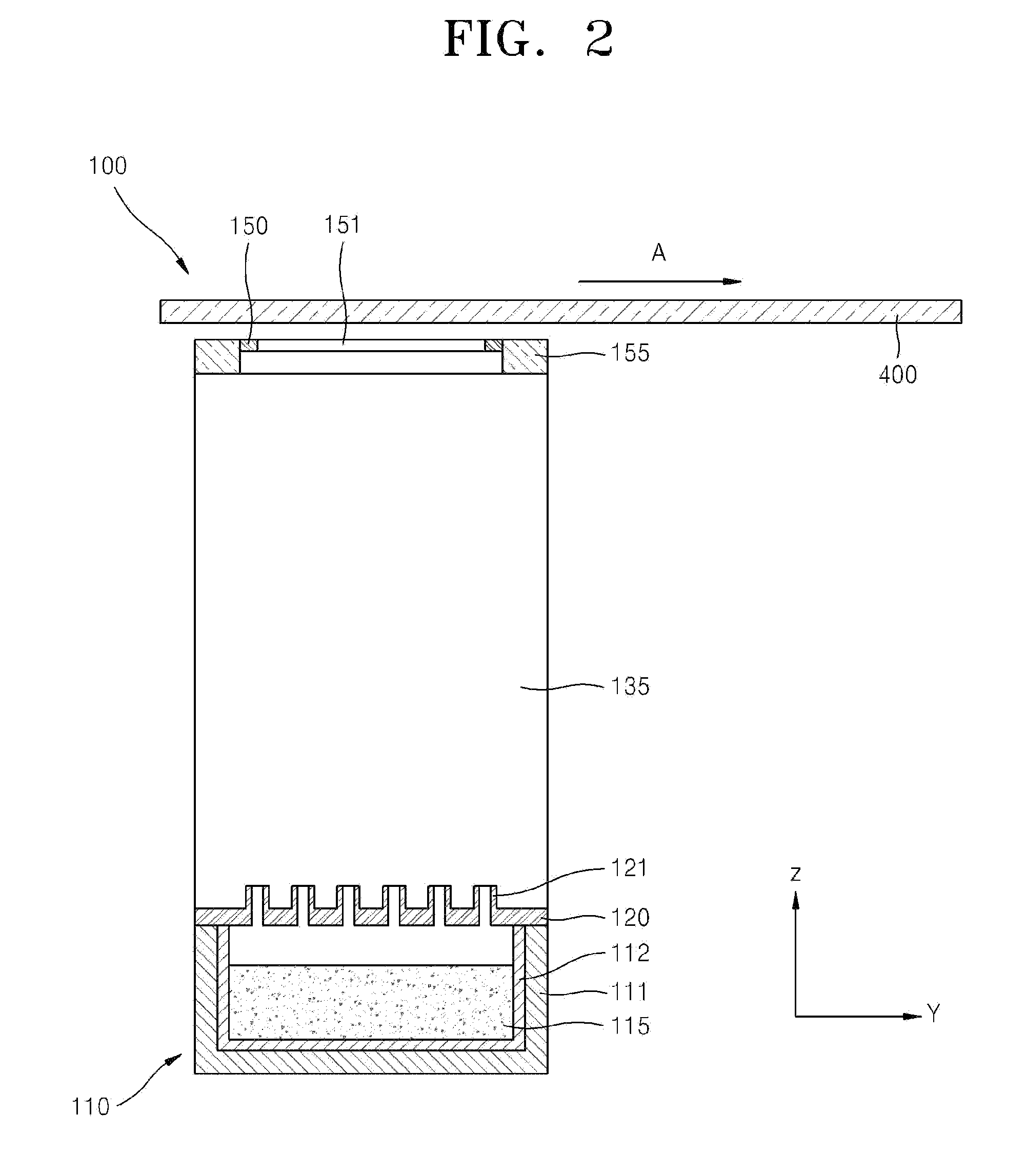
[0035]FIG. 1 is a schematic perspective view of a thin film deposition apparatus 100 including a patterning slit sheet 150 according to an embodiment of the present invention, FIG. 2 is a schematic side view of the thin film deposition apparatus 100 of FIG. 1 in the Y-Z plane, and FIG. 3 is a schematic plan view of the thin film deposition apparatus 100 of FIG. 1 in the X-Z plane. Referring to FIGS. 1, 2 and 3, the thin film deposition apparatus 100 according to the current embodiment of the present invention includes a deposition source 110, a deposition source nozzle unit 120, and a patterning slit sheet 150.

[0036]Although a chamber is not illustrate...


PUM

PropertyMeasurementUnit
Forceaaaaaaaaaa
Distanceaaaaaaaaaa
Tensionaaaaaaaaaa

Abstract

A tension apparatus for extending a patterning slit sheet included in a thin film deposition apparatus that can be simply applied to produce large-sized display devices on a mass scale and that improves manufacturing yield. The tension apparatus, wherein a plurality of patterning slits are formed along a first direction in the patterning slit sheet, and distances between adjacent patterning slits are different from each other, includes: a light source disposed to face the patterning slit sheet and irradiating light toward the patterning slit sheet; a tension member combined to at least one end of the patterning slit sheet, and applying a predetermined tensile force on the patterning slit sheet; and a master glass onto which light irradiated from the light source and passed through the patterning slit sheet is projected.

Description

CROSS-REFERENCE TO RELATED APPLICATION[0001]This application claims the benefit of Korean Application No. 10-2010-0066992, filed Jul. 12, 2010 in the Korean Intellectual Property Office, the disclosure of which is incorporated herein by reference.BACKGROUND[0002]1. Field[0003]One or more aspects of the present invention relate to a tension apparatus for a patterning slit sheet, and more particularly, to a tension apparatus for extending a patterning slit sheet included in a thin film deposition apparatus that can be simply applied to produce large-sized display devices on a mass scale and that improves manufacturing yield.[0004]2. Description of the Related Art[0005]Organic light-emitting display devices have a larger viewing angle, better contrast characteristics, and a faster response rate than other display devices, and thus have drawn attention as next-generation display devices.[0006]Organic light-emitting display devices generally have a stacked structure including an anode, a...

Claims


Application Information

Patent Timeline
12 Jan 2012
Publication
US20120006259A1
IPC
B05C11/00; G02B26/02
CPC
C23C14/044; C23C14/048; C23C14/56; C23C14/50; C23C14/54; C23C14/24
Inventors
SUNG, UN-CHEOL; KIM, MU-HYUN