Method of automatic target angle tracking by sum-and-difference monopulse radar and device therefore

Inactive Publication Date: 2012-01-12
MARKIN EVGENY
View PDF0 Cites 25 Cited by
  • Summary
  • Abstract
  • Description
  • Claims
  • Application Information

AI Technical Summary

Benefits of technology

[0018]The essence of the invention consists in the assurance of reliability and stability and in the enhancement of guidance accuracy of automatic target angle tracki

Problems solved by technology

It is commonly known that the presence of antenna cross-polarization radiation leads to reduction of direction finding accuracy; it can result in the complete failing of the monopulse direction finding system, i.e. automatic tracking loss /1/ (Chapters 6,8).
But this problem is most important when so-called polarization interference is used as electronic countermeasures means See /1/, paragraph 8.5.2, see also /2/).
However, the drawback of the abovementioned method is the necessity of doubling in the number of monopulse direction-finder reception channels (six instead of three), that makes this method virtually unacceptable for usage in, for example, the air-borne equipment of aerial vehicles and the like due to weight and size restrictions.
However the presence of diffraction effect on the edges of the polarization array doesn't allow to get a cross polarization level less than minus 35 dB (see /1/, p.
Besides that this mode is often inefficient when the monopulse direction-finder antenna is located under the blister (for example, an airplane or an unmanned aerial vehicle).
The blister owing to the curvilinearity of i

Method used


Image

  • Method of automatic target angle tracking by sum-and-difference monopulse radar and device therefore
  • Method of automatic target angle tracking by sum-and-difference monopulse radar and device therefore
  • Method of automatic target angle tracking by sum-and-difference monopulse radar and device therefore

Examples


example 1

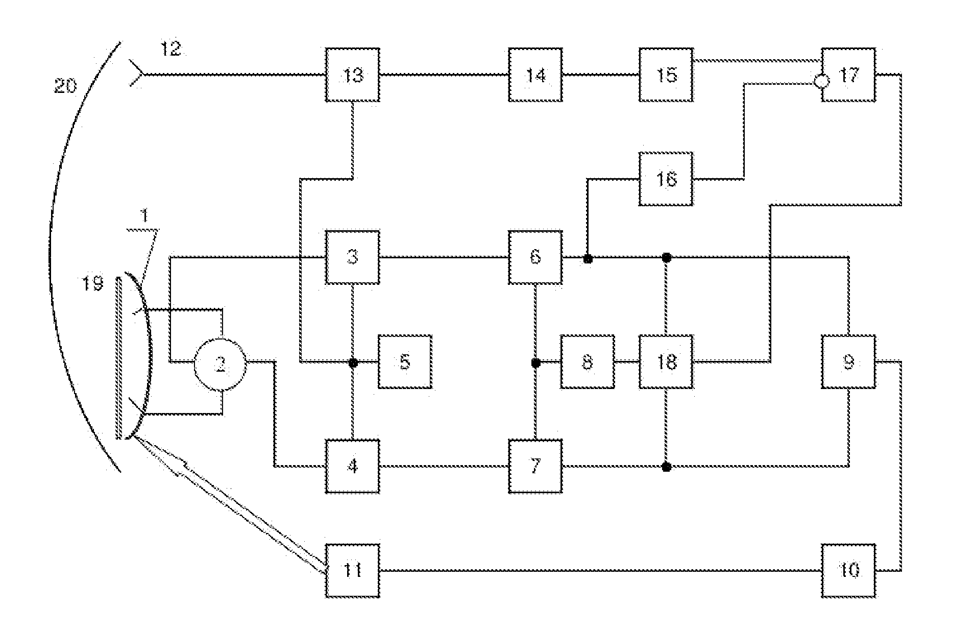
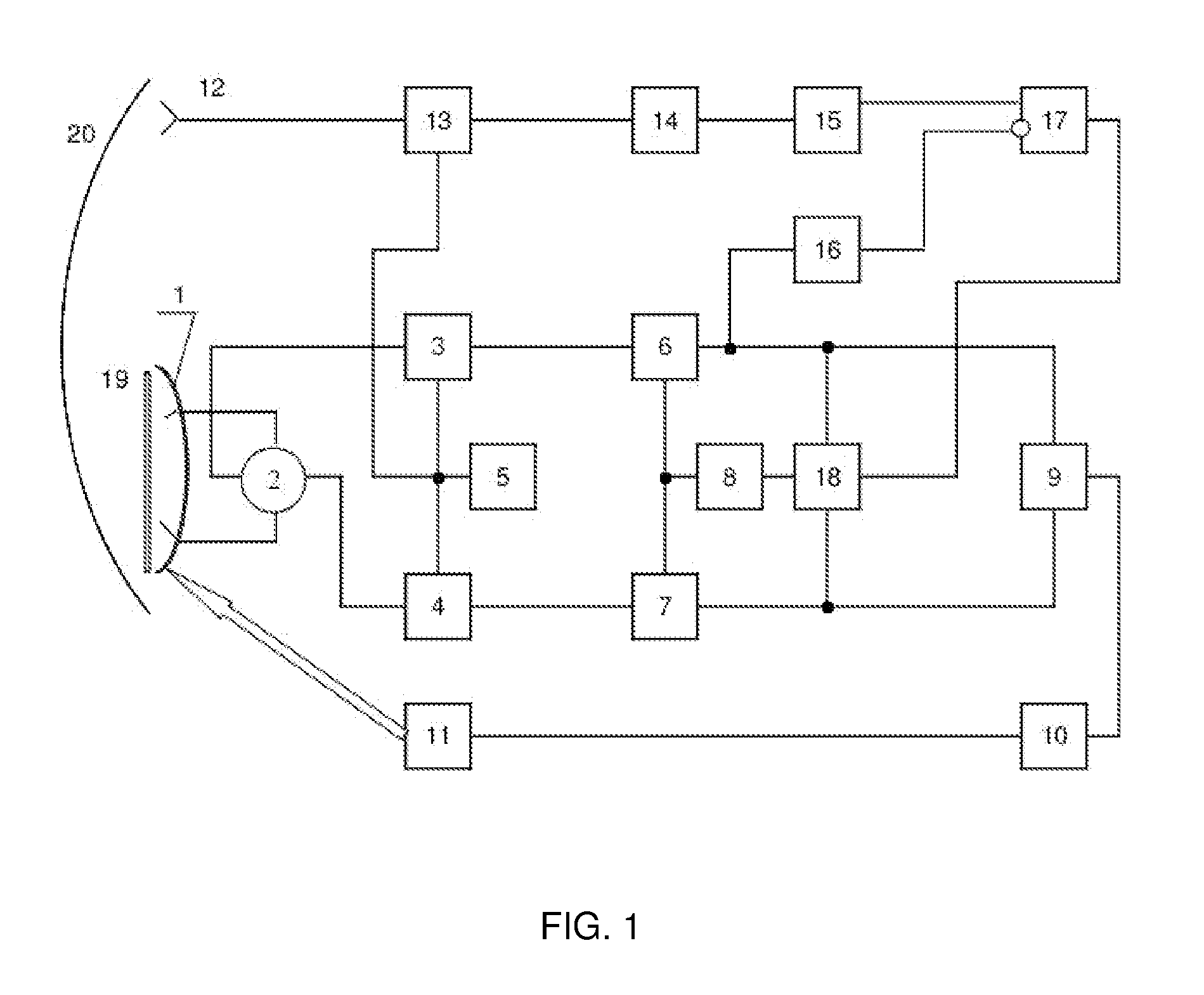
[0073]The radio direction-finder (FIG. 1) comprises monopulse antenna (for example, a paraboloid of revolution with two-mode feed) in the mouth of which a polarization filter 19 is mounted. The working polarization for antenna 1 is a vertical one. The outputs of antenna 1 are connected to the sum-and-difference device in the form of stripline ring 2, the sum output of which is connected to mixer 3 and the difference output—to mixer 4. Mixers 3 and 4 are also connected to heterodyne 5 which is also connected to mixer 13. The signal input of mixer 13 is connected to horn antenna 12 having the horizontal working polarization (orthogonal relative to the working polarization of monopulse antenna 1) and aperture (mouth) area 0.5 . . . 1.2λ2, which is mounted on the edge of antenna 1. The outputs of mixers 3 and 4 are connected respectively to the inputs of intermediate-frequency amplifiers 6 and 7, the outputs of which are connected to the appropriate inputs of phase detector 9, the outpu...

example 2

[0109]The radio direction-finder (FIG. 12) includes monopulse antenna (for example, a paraboloid of revolution with two-mode feed) in the mouth of which polarization filter 19 is mounted. The working polarization for antenna 1 is a vertical one. The outputs of antenna 1 are connected to the sum-and-difference device in the form of stripline ring 2, the sum output of which is connected to mixer 3 and the difference output—to mixer 4. Mixers 3 and 4 are also connected to heterodyne 5 which is also connected to mixer 13. The signal input of mixer 13 is connected to horn antenna 12 having the horizontal working polarization (orthogonal relative to the working polarization of monopulse antenna 1) and aperture (mouth) area 0.5 . . . 1.2λ2, which is mounted on the edge of antenna 1. The outputs of mixers 3 and 4 are connected respectively to the inputs of intermediate-frequency amplifiers 6 and 7. The output of intermediate-frequency amplifier 6 is connected to the input of automatic gain ...


PUM


Abstract

Method of automatic target angle tracking by sum-and-difference monopulse radar covers radiolocation sphere and specifically monopulse direction finding systems. It can be used in order to increase guidance accuracy, for example, for anti aircraft missiles and of unmanned aerial vehicles to radar targets such as: radio beacons; aerial vehicles reflecting the radio signal that illuminates them; aerial vehicles and ground-based devices radiating radio signals and jamming signals. The aim of the method consists in the assurance of reliability and stability and in the enhancement of guidance accuracy of automatic target angle tracking due to elimination of automatic tracking losses and great errors arising during the influence of the signals of orthogonal polarization or polarization close to it.
The proposed method provides full protection from polarization jamming for all types of monopulse radars.

Description

[0001]The invention relates generally to radiolocation sphere, and particularly to monopulse direction finding systems. It can be used to increase guidance accuracy, for example, of unmanned aerial vehicles to radar targets such as: radio beacons; aerial vehicles reflecting the radio signal that illuminates them; aerial vehicles and ground-based devices radiating radio signals and jamming signals.[0002]It is commonly known that the presence of antenna cross-polarization radiation leads to reduction of direction finding accuracy; it can result in the complete failing of the monopulse direction finding system, i.e. automatic tracking loss / 1 / (Chapters 6,8). The said phenomenon occurs during direction finding of the targets with marked depolarization effect which is the majority of real aerodynamic targets possess. But this problem is most important when so-called polarization interference is used as electronic countermeasures means See / 1 / , paragraph 8.5.2, see also / 2 / ).[0003]A meth...

Claims


Application Information

Patent Timeline
IPC IPC(8): G01S13/68G01S13/44
CPCG01S3/043G01S3/325H01Q25/02G01S13/4409H01Q19/17G01S7/025
Inventor MARKIN, EVGENY
Owner MARKIN EVGENY
Why Eureka
Try Eureka