
Multiple-Input Method And Apparatus Of Free-Space Optical Communication

a multi-input, optical communication technology, applied in the direction of electrical equipment, electromagnetic transmission, transmission, etc., can solve the problems of fading of received signals, requiring bulky hardware components, and being susceptible to scintillation

Active Publication Date: 2012-01-12
LGS INNOVATIONS
View PDF24 Cites 62 Cited by
  • Summary
  • Abstract
  • Description
  • Claims
  • Application Information

AI Technical Summary

Benefits of technology

[0005]We have provided a new solution, which makes use of the fact that different wavelengths will generally exhibit different fading characteristics in a propagation environment characterized by atmospheric scintillation. Our solution offers the possibility of open-loop adaptive processing that may be done purely in high-speed electronics. This allows for coherent processing across the wavefront and enables optical MIMO by taking advantage of the multipath propagation produced by the atmosphere.

Problems solved by technology

One of the known drawbacks of FSO is its susceptibility to scintillation.
The distortions cause time-dependent, destructive self-interference of the beam at the detector, which leads, in turn, to fading of the received signal.
However, such solutions require bulky hardware components.
Some of them also use a closed, iterative control loop of sensing and mechanical actuation that limits their performance.
These drawbacks are particularly severe in the case of QAM and other advanced modulation methods for the FSO beam, for which reception is relatively sensitive to the fidelity of the amplitude and phase of the received signal.

Method used


Image

  • Multiple-Input Method And Apparatus Of Free-Space Optical Communication
  • Multiple-Input Method And Apparatus Of Free-Space Optical Communication
  • Multiple-Input Method And Apparatus Of Free-Space Optical Communication

Examples


Embodiment Construction

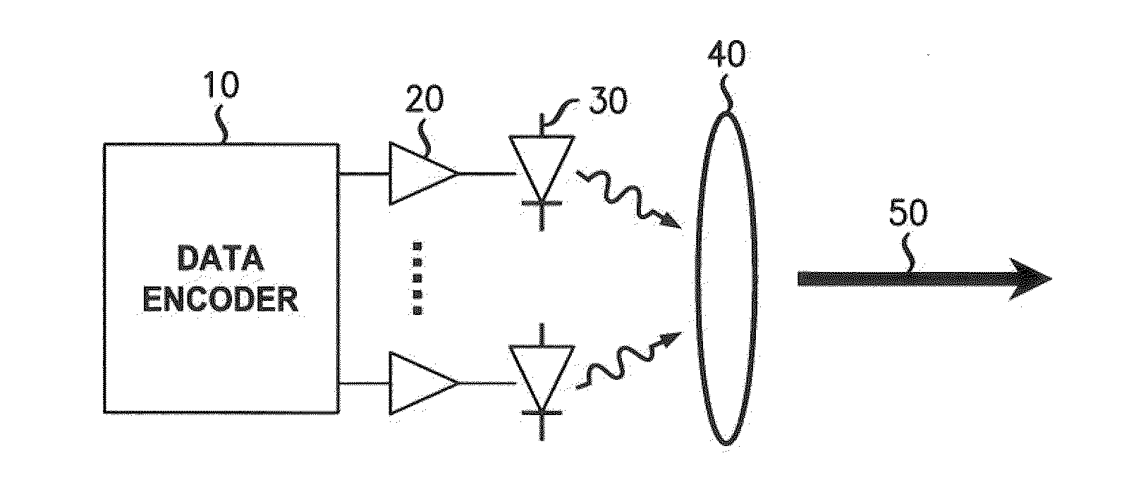
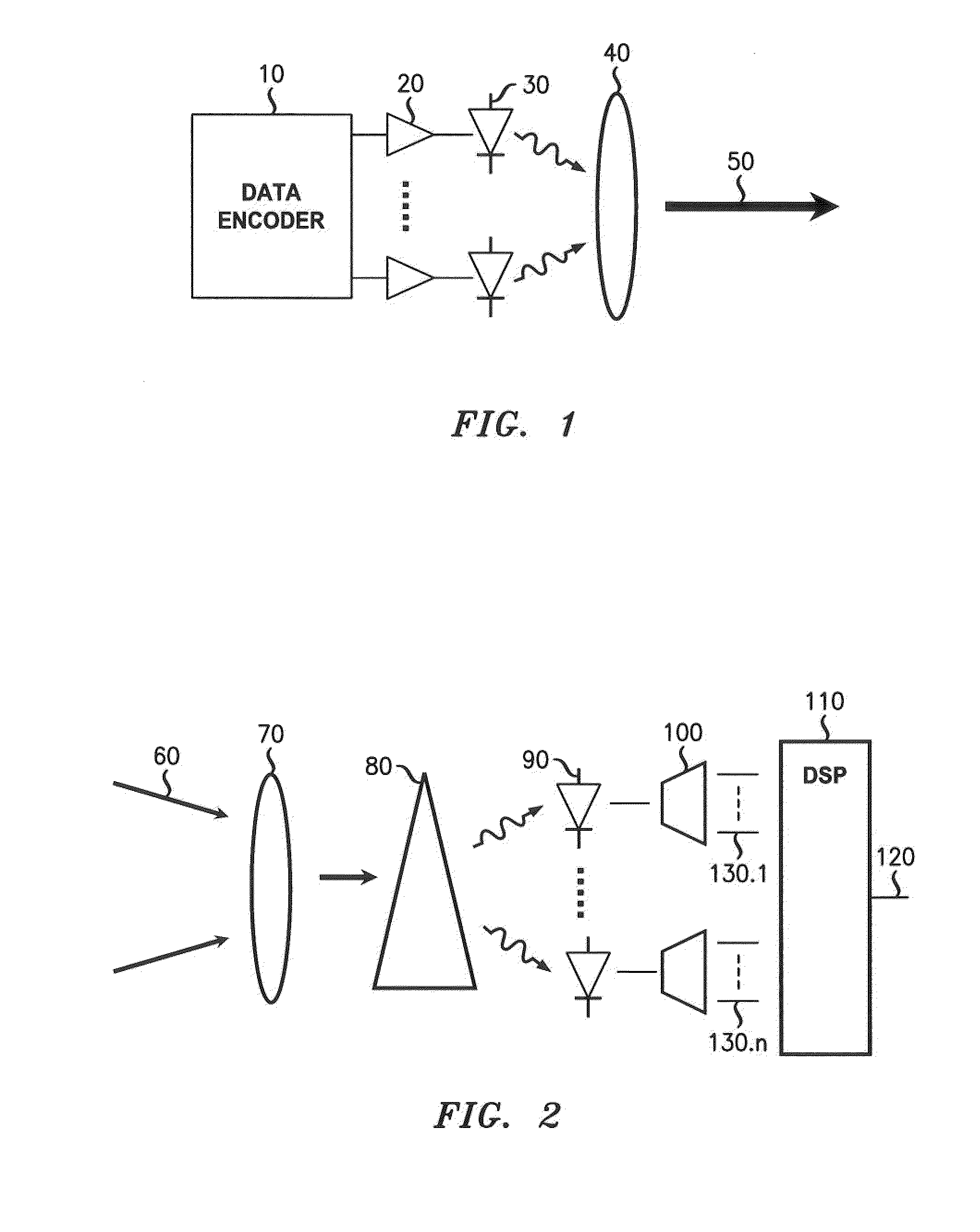
[0012]Turning to FIG. 1, an exemplary FSO transmitter includes a data encoder 10 for producing coded electrical signals that are applied after amplification stage 20 to modulate the optical output of two or more diode lasers 30. As seen in the figure, an optical system 40, which combines the functions of wavelength multiplexer and telescope, combines the optical outputs from the lasers into a beam 50 that is projected through space, typically through the atmosphere, toward a receiver.

[0013]Although only a single projected, wavelength-multiplexed output beam 50 is shown for simplicity of presentation, it will be understood that some advantages of spatial diversity may be achieved through arrangements in which multiple wavelength-multiplexed output beams are produced. This may be done, for example, by using multiple transmit apertures.

[0014]Numerous alternative implementations of the system shown conceptually in FIG. 1 will be apparent to those skilled in the art, using known techniqu...


PUM


Abstract

An approach is provided that uses diversity to compensate fading of free-space optical (FSO) signals propagating through an environment characterized by atmospheric scintillation. One embodiment involves collecting at least one FSO beam, demultiplexing the beam by wavelength into at least two sub-beams, detecting each sub-beam to produce an electrical output therefrom, and recovering a signal using complementary information from at least two of the electrical outputs. Another embodiment involves collecting the FSO beam onto an array of spatially separated sub-apertures, detecting the light entering each sub-aperture to produce an electrical output therefrom, and recovering a signal using complementary information from at least two of the electrical outputs. This second embodiment enables both electronic adaptive processing to coherently integrate across the sub-apertures and in the case of multiple transmit apertures a free space optical Multiple Input Multiple Output (MIMO) system.

Description

FIELD OF THE INVENTION[0001]This invention relates to free-space optical communication.ART BACKGROUND[0002]The advantages of free-space optical communication (FSO), such as high bandwidth and high signal directivity, have long been known. One of the known drawbacks of FSO is its susceptibility to scintillation. That is, turbulence and thermal phenomena create localized fluctuations in the atmospheric refractive index. A signal-carrying FSO beam passing through such fluctuations may be wholly or partially deflected due to optical refraction. One consequence is that at the receiving end, where the beam is focused onto an image spot, the image spot may wander in the image plane.[0003]Moreover, FSO beams are typically generated as coherent laser beams. A coherent beam initially has a uniform wavefront, i.e., a phase that varies slowly with radial position over the leading face of the beam. A beam having a uniform wavefront is desirable because at the detector, it will experience relativ...

Claims


Application Information

Patent Timeline
IPC IPC(8): H04B10/00
CPCH04B10/1121H04B10/11H04B10/613
Inventor CHEN, YOUNG-KAIKANEDA, NORIAKIPIDWERBETSKY, ALEX
Owner LGS INNOVATIONS
Learn More