Method of fabricating microfluidic systems

a microfluidic system and microfluidic technology, applied in the field of microfluidic systems, can solve the problems of poor channel resolution and definition, rigid and brittle barriers which can be easily damaged, physical barriers which define the periphery of microchannels, etc., and achieve the effect of fast change and low cos

Active Publication Date: 2012-01-12
MONASH UNIV
View PDF3 Cites 17 Cited by
  • Summary
  • Abstract
  • Description
  • Claims
  • Application Information

AI Technical Summary

Benefits of technology

[0032]Compared with the previous physical barrier fabrication methods, the new fabrication method according to the present invention enables the manufacturing of paper-based microfluidic devices in commercial scales and at low cost. Creation of hydrophilic-hydrophobic contrast is a simpler approach to define liquid penetration channels in paper than the physical barrier approach.
[0033]The use of digital printing technology to selectively deliver cellulose hydrophobization chemicals on paper surface to form the hydrophilic-hydrophobic contrast has some other advantages. Digital printing offers electronic pattern variation which allows fast change over for fabrication of different devices. Since the hydrophilic-hydrophobic contrast fabrication concept can retain the original flexibility of the paper, it offers natural bending and folding resistance, which fundamentally overcomes the poor bending and folding resistance often encountered with devices fabricated with other methods. These attributes are particularly attractive for personal care device applications such as in a diaper indicator application for example.

Problems solved by technology

A problem associated with the use of such photolithography techniques is that they result in rigid and brittle barriers which can be easily damaged if the paper is creased or crumpled.
Their second system, however, has a poor channel resolution and definition, since the penetration of PDMS solution in paper sheet cannot be controlled.
Both fabrication approaches result in physical barriers which define the periphery of the micro-channels.
However all of the above-noted systems utilise complex and time consuming processes that cannot be readily adapted to allow for low cost, high speed industrial production.
Furthermore, all these earlier systems rely on a physical barrier to define the microfluidic channels.

Method used


Image

  • Method of fabricating microfluidic systems
  • Method of fabricating microfluidic systems
  • Method of fabricating microfluidic systems

Examples


example 1

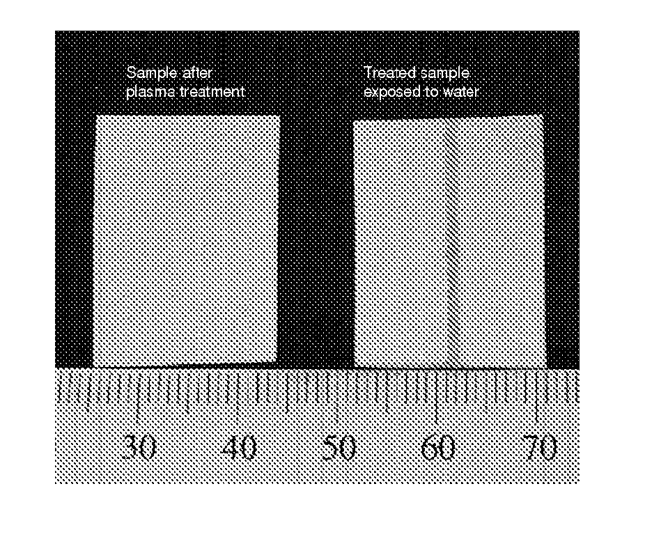
[0047]In one embodiment of the invention as shown in FIG. 1, a filter paper was hydrophobized by immersion in a solution of AKD dissolved in heptane and the solvent was allowed to evaporate. A heat treatment of the treated paper in an oven at 100° C. for 30-50 minutes was applied. In the second step, a solid mask was applied to the paper substrate and the system was exposed to a plasma reactor (K1050X plasma asher (Quorum Emitech, UK) for 10-100 seconds at the intensity of 12-50 W). The plasma treatment left no visible mark on the sample and the sample retained its original softness and flexibility. The treated channel becomes wettable by aqueous solutions and allows the capillary transport of the solutions. The width of the channel can be well controlled. FIG. 1 shows a single channel treated with a mask of 1 mm in width on filter paper, and shows the channel before and after wetting by water.

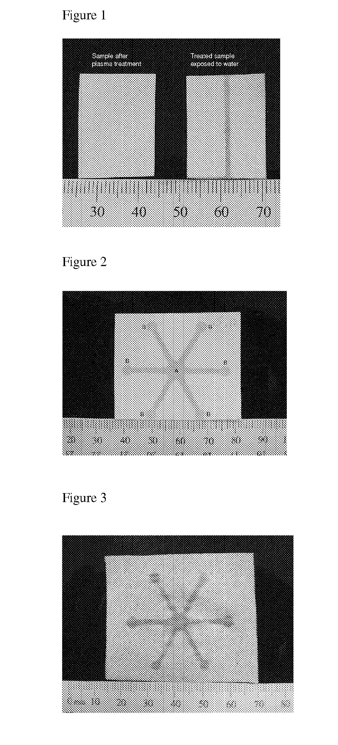
[0048]The treated channel can have any geometrical pattern as shown in FIG. 2. First, a pa...

example 2

[0050]In a second embodiment of the invention as shown in FIG. 3, micro-channels were formed onto composites cellulosic materials. A two-ply Kleenex mainline facial tissue was treated similarly to example 1. FIG. 3 represents the liquid filled micro-channels on Kleenex two-ply tissue.

example 3

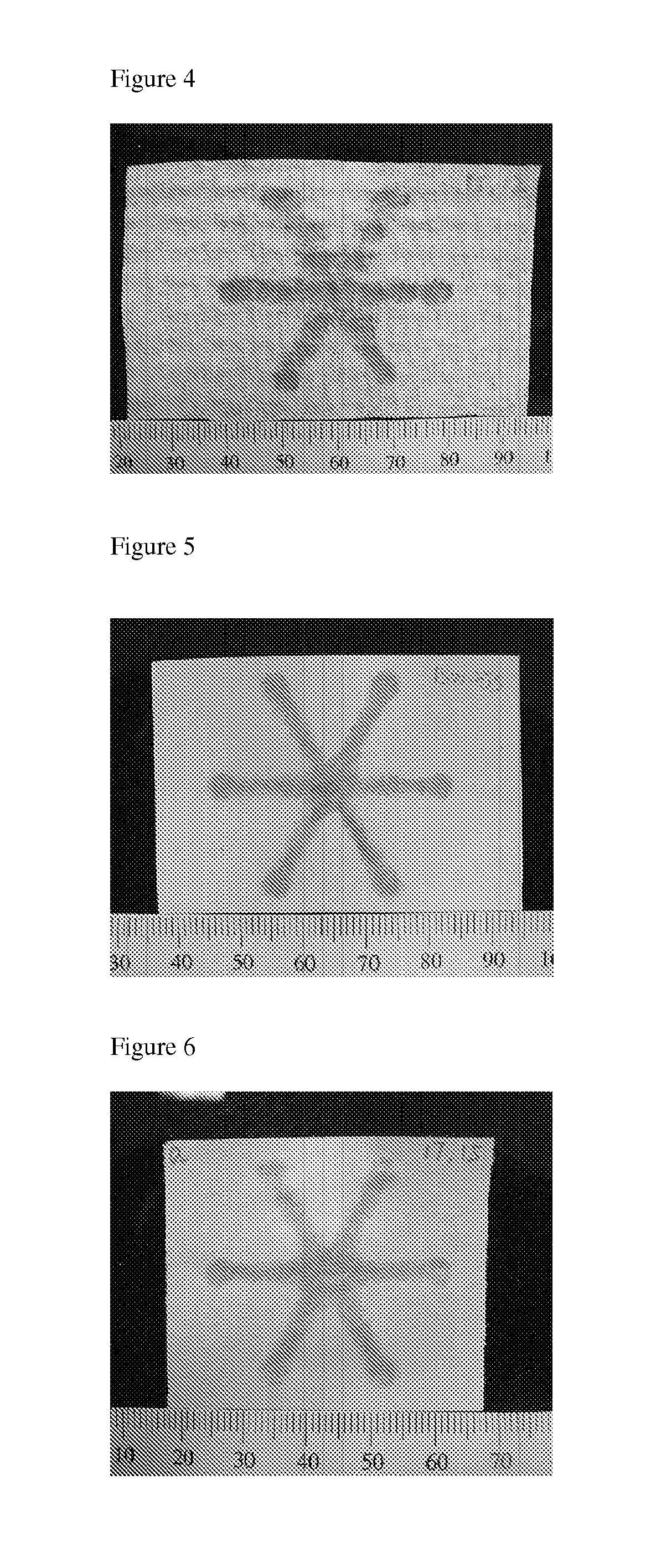
[0051]In a third embodiment of the invention as shown in FIG. 4, micro-channels were formed onto a layered and molded paper basesheet. A three-layer molded paper towel (Kimberly-Clark Viva) was treated similarly to example 1. FIG. 4 represents the liquid filled micro-channels on three-layer Kimberly-Clark Viva towel.


PUM

PropertyMeasurementUnit
widthaaaaaaaaaa
lengthaaaaaaaaaa
widthaaaaaaaaaa

Abstract

A method of fabricating a microfluidic system having microfluidic channels on a surface of a hydrophilic substrate, the method including the steps of: hydrophobizing the substrate surface; locating a mask defining the substrate surface, the mask having open areas defining the periphery of the microfluidic channels; and applying an irradiation treatment to areas of the substrate surface exposed by the open areas of the mask, said exposed areas becoming hydrophilic to therefore form said microfluidic channels.

Description

TECHNICAL FIELD[0001]The present invention is generally directed to microfluidic systems, and fabrication of such systems on low cost substrates such as paper, woven fabric and non-woven cellulosic material.BACKGROUND TO THE INVENTION[0002]The concept of making inexpensive microfluidic channels on paper and other woven and non-woven fibrous and porous surfaces has been successfully proven. The aim of building such systems has been to fabricate low-cost bio-analytical and indicator devices, with direct envisaged applications in detecting waterborne bacteria and metals ions in drinking water, the presence of some specific proteins or biomarkers in body fluid (cancer test), the level of glucose and other bio-chemical substances in human or animal blood and urine samples. Developments of low-cost paper-based bio-analytical and environmental analytical devices have so far allowed quick and single step reaction to detect analytes in a fluid sample.[0003]Researchers in Harvard University l...

Claims


Application Information

Patent Timeline
Patent Type & Authority Applications(United States)
IPC IPC(8): C12M1/00G03F7/20
CPCB01L3/502707B01L2200/10B01L2200/12B01L2300/126Y10T436/11D21H17/16D21H17/17D21H19/10D21H21/16B01L2300/161
Inventor SHEN, WEILI, XUTIAN, JUNFEIKHAN, MOHIDUS SAMADGARNIER, GIL
Owner MONASH UNIV
Why Eureka
Try Eureka