
Ignition apparatus for plasma jet ignition plug and ignition system

a technology of ignition plug and ignition system, which is applied in the direction of electric ignition installation, mechanical equipment, machines/engines, etc., can solve problems such as dielectric breakdown, and achieve the effect of enhancing ignition performance and increasing plasma peak energy

Inactive Publication Date: 2012-01-19
NGK SPARK PLUG CO LTD
View PDF3 Cites 5 Cited by
  • Summary
  • Abstract
  • Description
  • Claims
  • Application Information

AI Technical Summary

Benefits of technology

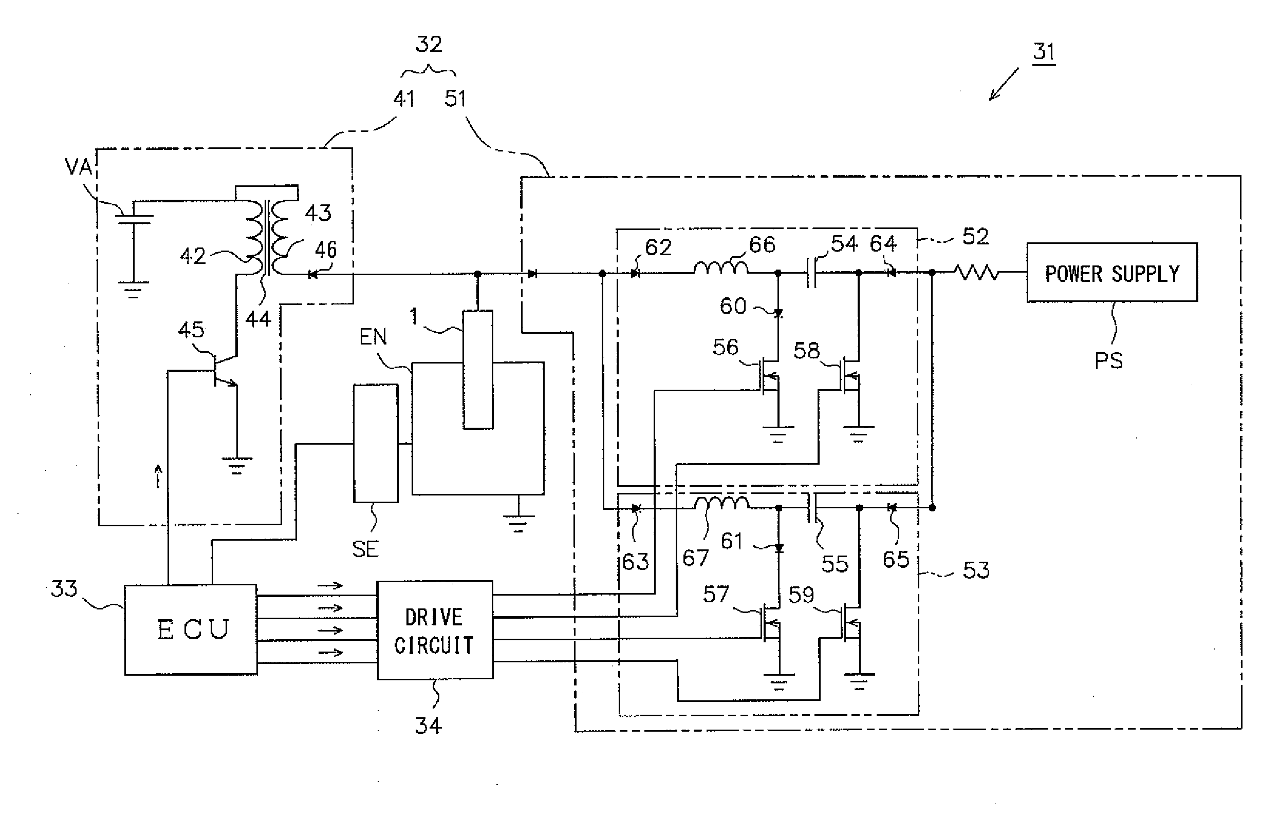
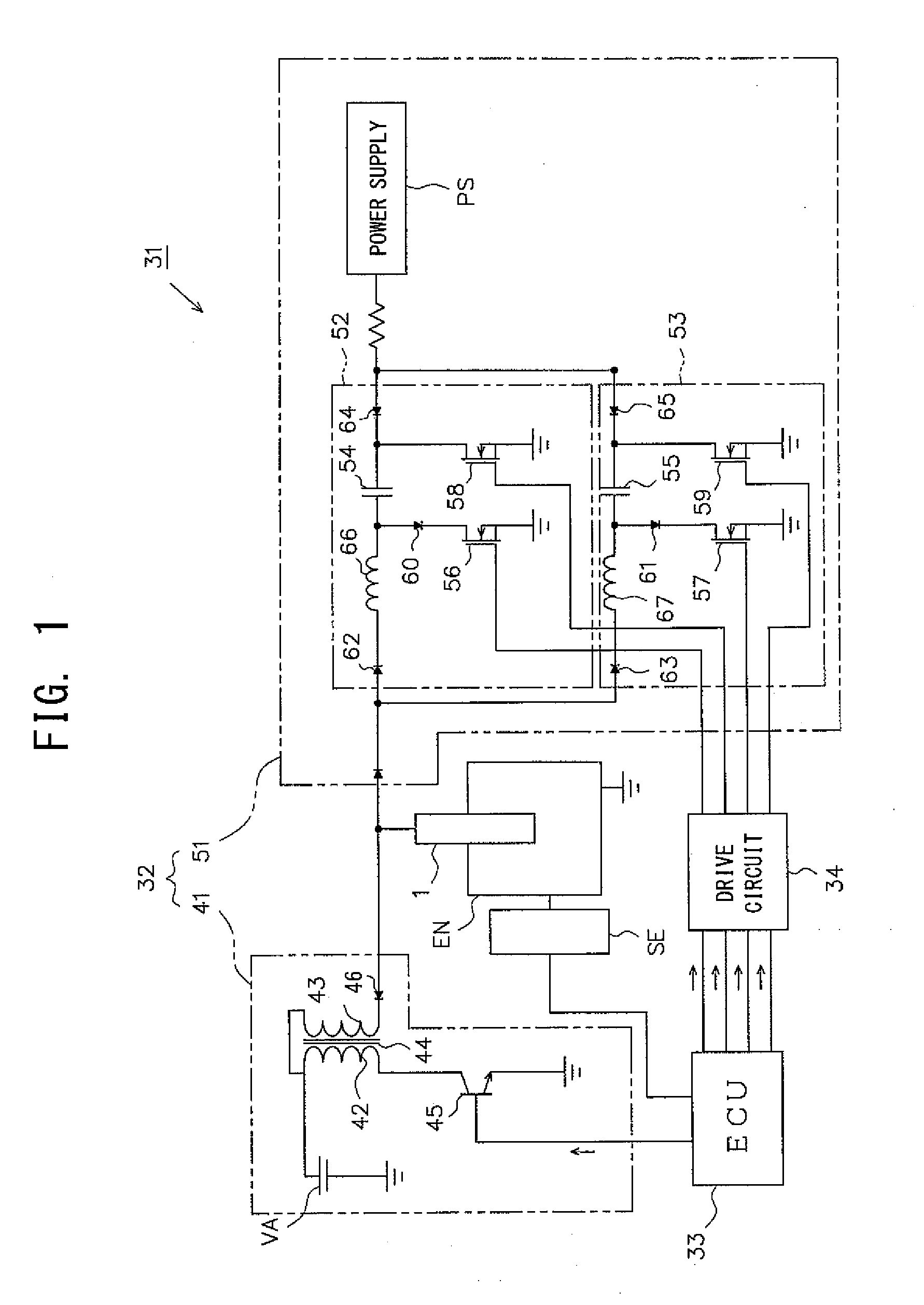
[0013]According to the above-described configuration 1, the capacitor is provided in series between the power supply which generates positive voltage and the ignition plug. Therefore, in a state in which the capacitor is charged, the side of the capacitor connected to the power supply becomes positive, and the side of the capacitor connected to the ignition plug becomes negative. Accordingly, when electric energy is supplied from the capacitor to the ignition plug, current flows from the ignition plug to the capacitor (that is, the center electrode serves as a negative electrode for generation of plasma). Thus, the ignition plug generates both spark discharge and plasma while using the center electrode as a negative electrode. Therefore, ignition performance and the erosion resistance of the electrodes can be enhanced.
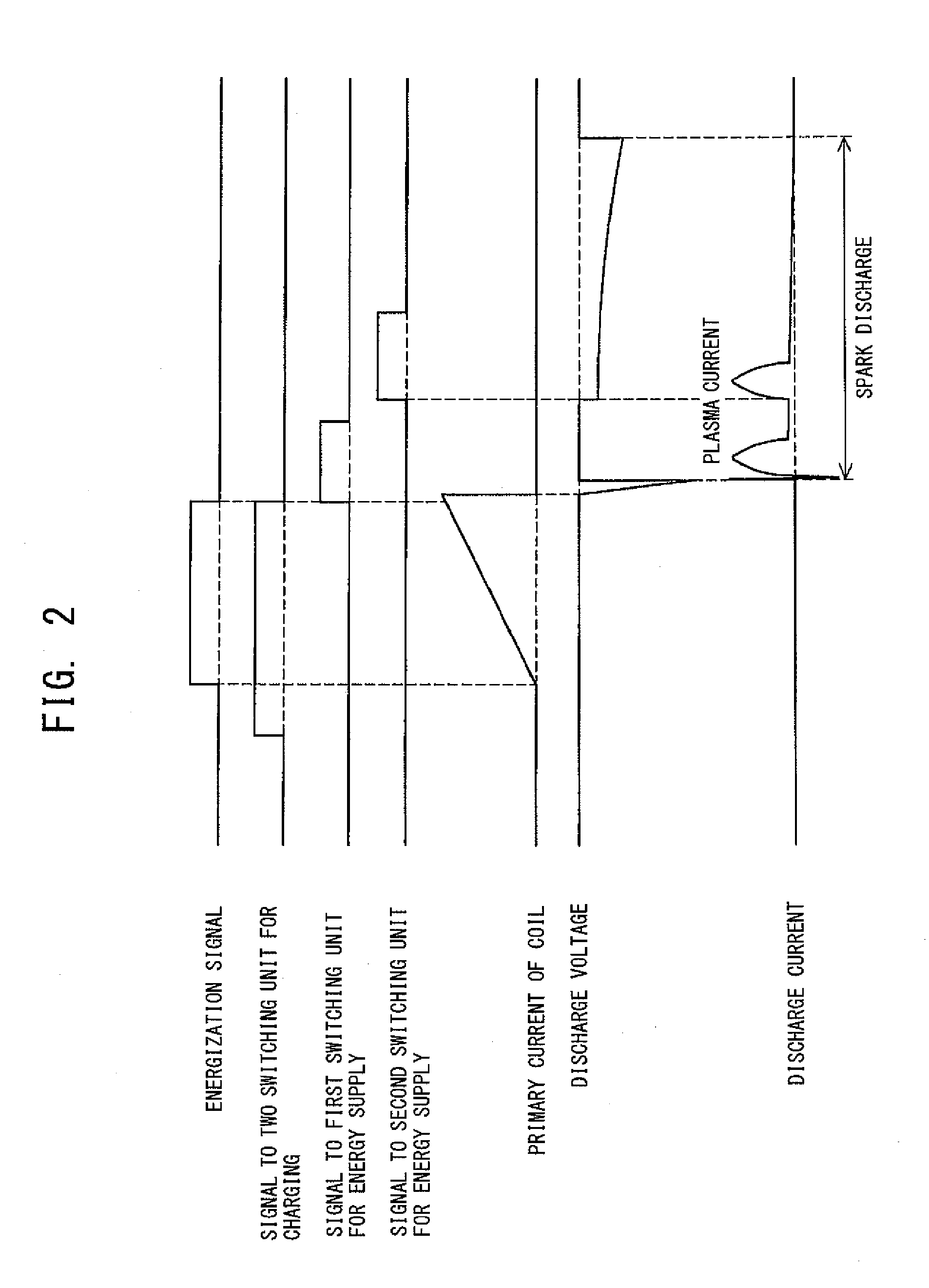
[0035]According to the above-described configuration 8, in synchronism with a timing at which at least one capacitor supplies electric energy, electric energy is charged into at least one capacitor, other than the capacitor supplying electric energy. Accordingly, without provision of a large number of energy supply unit, it becomes possible to supply electric energy from a single capacitor a plurality of times during a single spark discharge, whereby plasma of various forms can be generated more easily.

Problems solved by technology

First, voltage is applied between the center electrode and the ground electrode, thereby generating spark discharge therebetween and thus causing dielectric breakdown therebetween.

Method used


Image

  • Ignition apparatus for plasma jet ignition plug and ignition system
  • Ignition apparatus for plasma jet ignition plug and ignition system
  • Ignition apparatus for plasma jet ignition plug and ignition system

Examples


Embodiment Construction

[0042]An embodiment of the present invention will next be described with reference to the drawings. FIG. 1 is a block diagram schematically showing the configuration of an ignition system 31 including an ignition apparatus 32 for a plasma jet ignition plug (hereinafter, referred to as the “ignition plug”) 1; and an electronic control unit (ECU) 33 of a vehicle, which serves as control unit for controlling the ignition apparatus 32.

[0043]First, the structure of the ignition plug 1, which is controlled by the ignition system 31, will be described briefly before description of the ignition system 31.

[0044]FIG. 6 is a partially cutaway front view showing the ignition plug 1. In FIG. 6, the direction of an axis CL1 of the ignition plug 1 is referred to as the vertical direction. In the following description, the lower side of the spark plug 1 in FIG. 6 is referred to as the front side of the spark plug 1, and the upper side as the rear side.

[0045]The ignition plug 1 includes a tubular in...


PUM


Abstract

An ignition apparatus for an ignition plug which uses a positive polarity power supply, which can cause the ignition plug to generate spark discharge while using its center electrode as a negative electrode, and which can adjust the timing of supply of electric energy to the ignition plug and the timing of charging of capacitors. The ignition apparatus is adapted to cause the ignition plug to generate spark discharge while using its center electrode as a negative electrode, and includes a positive power supply, and energy supply units. Each energy supply unit includes a capacitor connected at one end to the power supply and connected at the other end to the ignition plug; a switching unit for charging; and a switching unit for energy supply.

Description

FIELD OF THE INVENTION[0001]The present invention relates to an ignition apparatus for a plasma jet ignition plug which ignites an air-fuel mixture through formation of plasma, and to an ignition system which includes the ignition apparatus.BACKGROUND OF THE INVENTION[0002]Conventionally, a combustion apparatus, such as an internal combustion engine, uses a spark plug for igniting an air-fuel mixture through spark discharge. In recent years, in order to meet demand for high output and low fuel consumption, a plasma jet ignition plug has been proposed, since the plasma jet ignition plug provides quick propagation of combustion and can more reliably ignite even a lean air-fuel mixture having a higher ignition-limit air-fuel ratio.[0003]Generally, the plasma jet ignition plug includes a tubular insulator having an axial hole, a center electrode inserted into the axial hole in such a manner that a front end surface thereof is located internally of a front end surface of the insulator, a...

Claims


Application Information

Patent Timeline
Patent Type & Authority Applications(United States)
IPC IPC(8): F02P3/09
CPCF02P9/007F02P3/09
Inventor NAKANO, DAISUKESATO, YOSHIKUNIKAMEDA, HIROYUKIYAMAMURA, NAOFUMIKASAHARA, DAISUKE
Owner NGK SPARK PLUG CO LTD
Learn More