
Hybrid flare apparatus and method

Inactive Publication Date: 2012-01-19
JOHN ZINK CO LLC
View PDF15 Cites 24 Cited by
  • Summary
  • Abstract
  • Description
  • Claims
  • Application Information

AI Technical Summary

Benefits of technology

[0062]The control unit of the second embodiment of the inventive flare assembly is for controlling the steam control valve and the alternative gas control valve. The control unit is responsive to the flow rate of the vent gas stream and capable of calculating a maximum allowable flow rate of primary steam through the steam injector assembly into the combustion zone and modulating the flow rate of primary steam through the steam injector assembly into the combustion zone to avoid a flow rate of steam in excess of the maximum allowable flow rate of steam.

Problems solved by technology

As a result, an integrated ignition system that can immediately initiate burning throughout the period of waste gas flow is critical.
In applications where the gas pressure is low, the momentum of the vent gas stream alone may not be sufficient to provide smokeless operation.
The steam jets inspirate air from the surrounding atmosphere and inject it into the discharged vent gas with high levels of turbulence.
Operation of a flare assembly in freezing conditions creates additional issues that must be addressed.
For example, when steam is discharged through the flare assembly at a low flow rate to cool the steam equipment when the flare is in a standby condition or to assist a low volume flaring event, freezing temperatures may cause the steam to condense and form ice on or around the flare tip.
Also, condensation can occur in the steam line running from the source of steam to the flare assembly.
In some cases, the steam line is very long and, despite the use of insulation, prone to condensation.
The formation of ice on or around the vent gas discharge opening, for example, can lead to blockage of the discharge opening and other serious problems.
However, when the vent gas flow begins to subside, the flare flame may continue to look “clean” to the operator, which may allow some time to pass before the operator reduces the steam flow.
As a result, this method of smoke control tends to result in over-steaming of the flare which in turn may lead to excessive noise and unnecessary steam consumption, low destruction and removal efficiency, or even extinguish the main flame altogether.
Too much steam can cause the ratio of the flow rate of steam discharged by the flare assembly to the flow rate of vent gas discharged by the flare assembly (the “steam / vent gas ratio”) to become too high, which can in turn reduce the net heating value of the flare gas in the combustion zone to a point that combustion cannot be sustained.
This can particularly be a problem when the vent gas flow rate is at a low level.
It can also be a problem when the flare assembly is in standby condition, and there is only minimum flow of purge gas through the stack.
Allowing the steam / vent gas ratio to exceed a certain level and the net heating value of the flare gas to become too low may violate one or more regulations relating to operation of the flare assembly.
As a result, it is difficult to specify simple operating parameters that ensure a high DRE and prevent over-steaming.
Furthermore, a lower rate of steam may not be sufficient to achieve smokeless operation, which may also violate applicable regulations regarding visible emissions and is undesirable in most applications.
Under some circumstances, both smoking and over-steaming, as legally defined by applicable regulations, cannot be avoided at the same time in a conventional steam assisted flare, no matter how the steam flow rate is adjusted.
Increasing the purge gas flow rate (as opposed to reducing the steam flow rate) may help with compliance but the costs of the increased purge gas may be prohibitive.
This can create a dilemma for owners of steam-assisted flares with respect to operation of the flare.
In view of these regulations, it may become even more difficult for a conventional steam-assisted flare assembly to achieve smokeless operation, prevent over-steaming and address other problems such those described above.
Simply reducing the amount of steam may not be a sufficient solution.

Method used


Image

  • Hybrid flare apparatus and method
  • Hybrid flare apparatus and method
  • Hybrid flare apparatus and method

Examples


Embodiment Construction

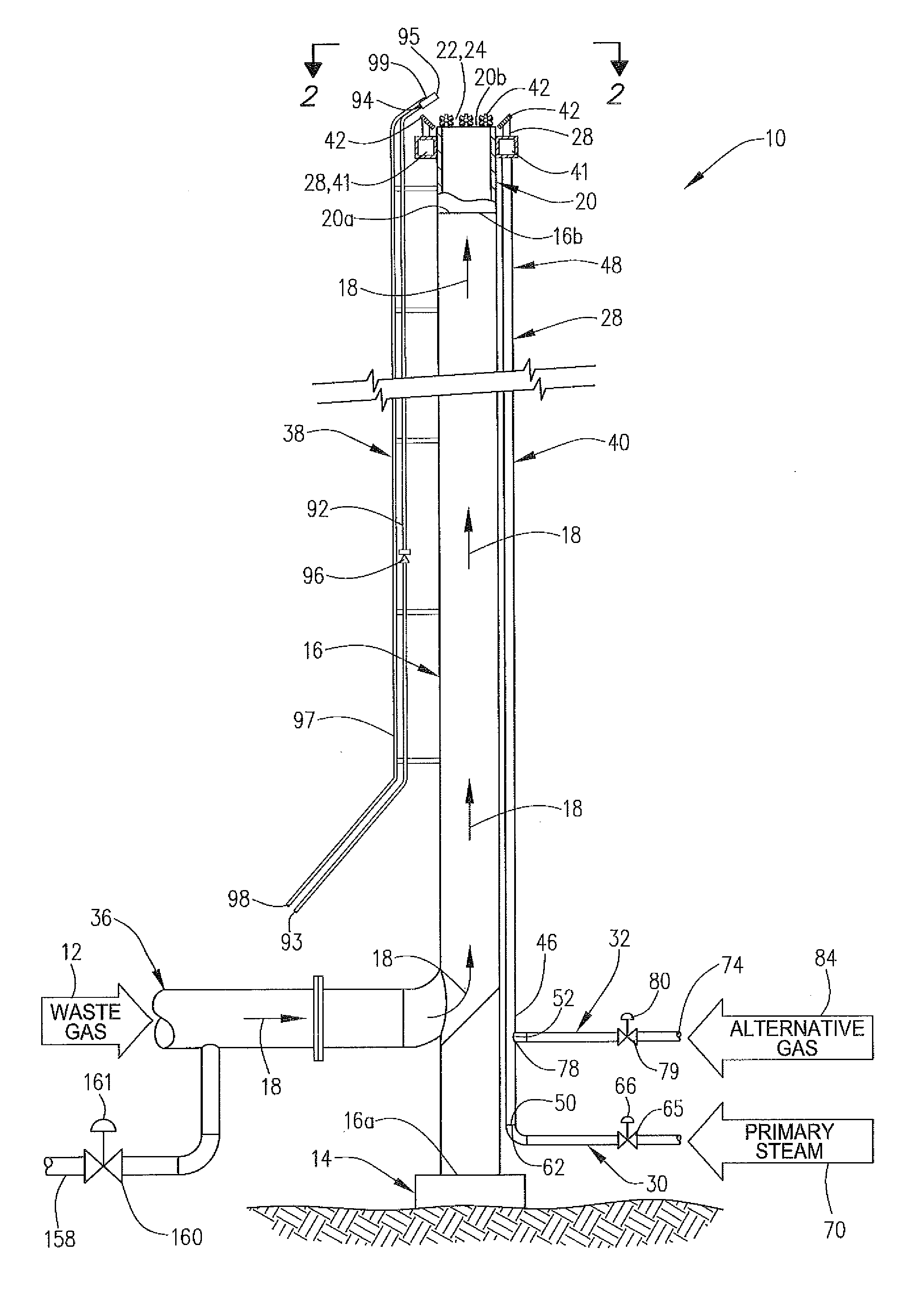
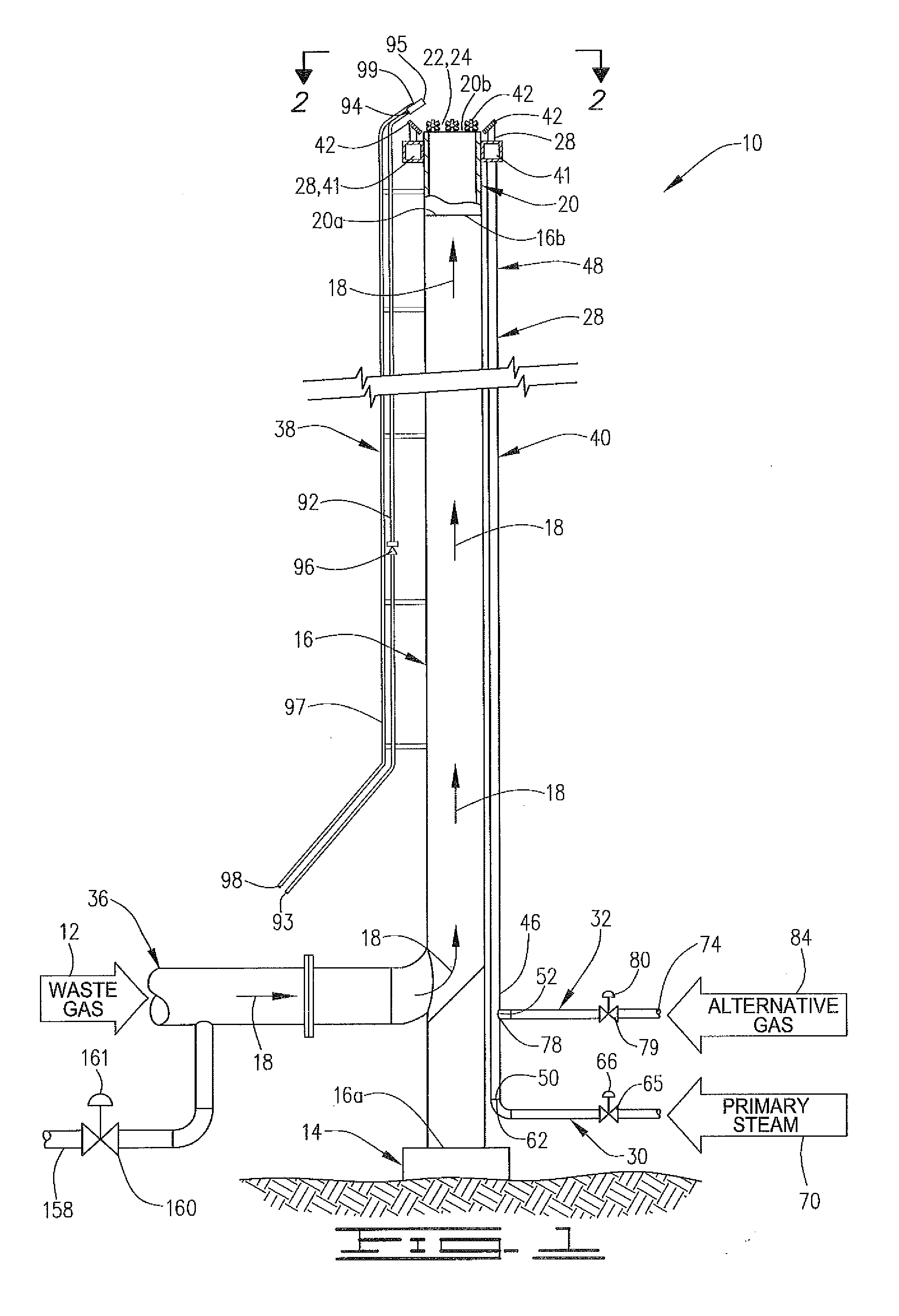
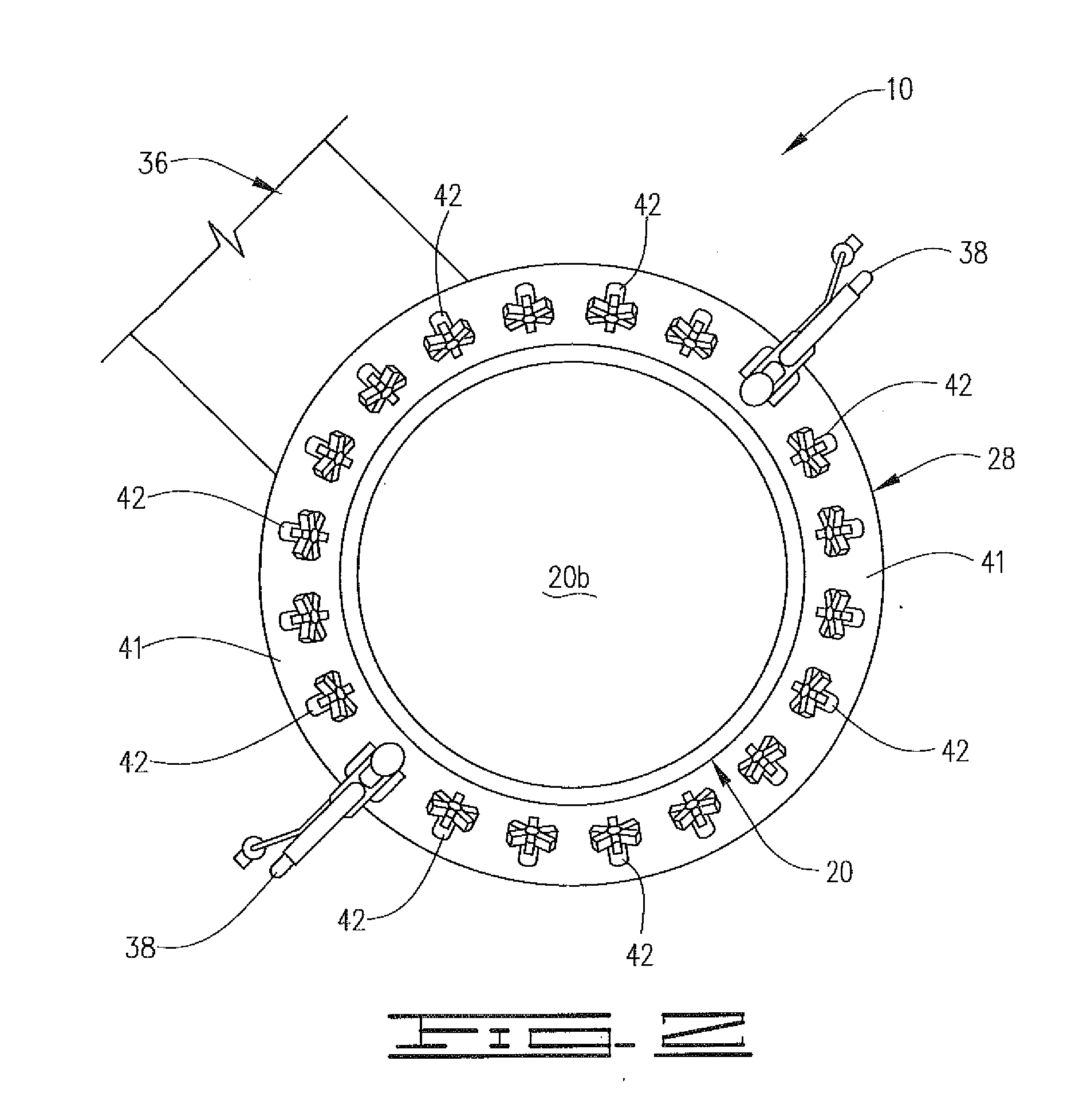
[0076]As used herein and in the appended claims, the terms set forth below shall have the following meanings:[0077]A “facility” means a production facility, refinery, chemical plant, processing plant or any other facility from which waste gas is released due to venting requirements, shut-downs, upsets, emergencies or other reasons.[0078]“Waste gas” means the organic material, nitrogen, and any other gases that are released from the facility for disposal and received by the flare assembly.[0079]“Vent gas” means the waste gas as defined above together with other gases and vapors, if any, added to the waste gas stream before the waste gas stream enters the flare tip of the flare assembly.[0080]“Flare gas” means the vent gas as defined above plus all other gases and vapors present in the atmosphere immediately downstream of the flare tip, not including air but including steam added at the flare tip and fuel gas discharged from the pilot(s) of the flare assembly.[0081]“Primary steam” mea...


PUM


Abstract

A method of operating a flare assembly is provided. If it is determined that the injection of primary steam into the combustion zone is necessary to achieve smokeless operation, primary steam is injected through a steam injector assembly into the combustion zone. If it is determined that steam is not necessary, an alternative gas is discharged though the steam injector assembly into the combustion zone. In one embodiment, the alternative gas is heated. In another embodiment, if it is determined that steam is necessary, a maximum allowable flow rate of steam is calculated, and the flow rate of steam is modulated to achieve smokeless operation and avoid a flow rate of steam in excess of the maximum allowable flow rate of steam. A flare assembly is also provided.

Description

BACKGROUND OF THE INVENTION[0001]Waste gas flare assemblies are commonly located at production facilities, refineries, processing plants and the like (collectively “facilities”) for disposing of flammable gas streams that are released due to venting requirements, shut-downs, upsets and / or emergencies. Such flare assemblies are typically required to accommodate waste gases that vary in composition over a wide range and operate over a very large turndown ratio (from maximum emergency flow to a purge flow rate) and extended periods of time without maintenance.[0002]A typical single-point flare assembly includes a flare riser, which can extend a few feet to several hundred feet above the ground, and a flare tip mounted to (e.g., in a vertical flare, on the top of) the flare riser. The flare tip typically includes one or more pilots for igniting the vent gas. Depending on the particular flare tip design and available gas pressure, some flares include smoke suppression equipment such as s...

Claims


Application Information

Patent Timeline
IPC IPC(8): F23G7/08
CPCF23G5/50F23N2021/10F23G7/085F23N2221/10F23G7/06F23G7/08F23L7/00
Inventor HONG, JIANHUIFRANKLIN, JAMES CHARLESKNOTT, DENNIS LEEKODESH, ZACHARY LEWISFOX, SCOTT JOSEPH
Owner JOHN ZINK CO LLC
Learn More