
Method for Optimizing Spin Time In a Centrifuge Apparatus for Biologic Fluid

Active Publication Date: 2012-01-19
TERUMO BCT
View PDF0 Cites 17 Cited by
  • Summary
  • Abstract
  • Description
  • Claims
  • Application Information

AI Technical Summary

Benefits of technology

[0006]It is an object of the present invention, therefore, to improve the efficiency of a centrifugal blood processing apparatus by reducing processing time. In particular, the invention uses iterative methods to correct processing time. The method employs regression analysis to correct a predicted spin time by determining when a red blood cell interface arrives at or crosses a sensing location. The method may comprise setting an initial hematocrit estimate at a high value; placing a detector at a selected location in a blood processing apparatus; detecting the arrival of a blood component interface at the selected location; re-determining an expected processing duration from the arrival time of the interface; and continuing to separate blood. Preferably, a sensor for detecting the arrival of the interface is placed at a location near one half nominal spin time, that is, near a location where an RBC (red blood cell) interface would be expected after centrifugation for about half of the expected processing time. Detection of the RBC interface allows the apparatus to predict an adjusted processing time from the difference between the expected RBC interface arrival time and the actual RBC interface arrival time.

Problems solved by technology

In general, a predicted processing time for separating a unit of whole blood into component parts may be inaccurate because of uncertainties in certain parameters.
If it is assumed that the hematocrit of the unit is high (to assure complete processing), the duration of processing will generally be longer than necessary, and the separation process overall will be less efficient.
This inefficiency would be compounded over many units of blood processed on many different machines.

Method used


Image

  • Method for Optimizing Spin Time In a Centrifuge Apparatus for Biologic Fluid
  • Method for Optimizing Spin Time In a Centrifuge Apparatus for Biologic Fluid
  • Method for Optimizing Spin Time In a Centrifuge Apparatus for Biologic Fluid

Examples


Embodiment Construction

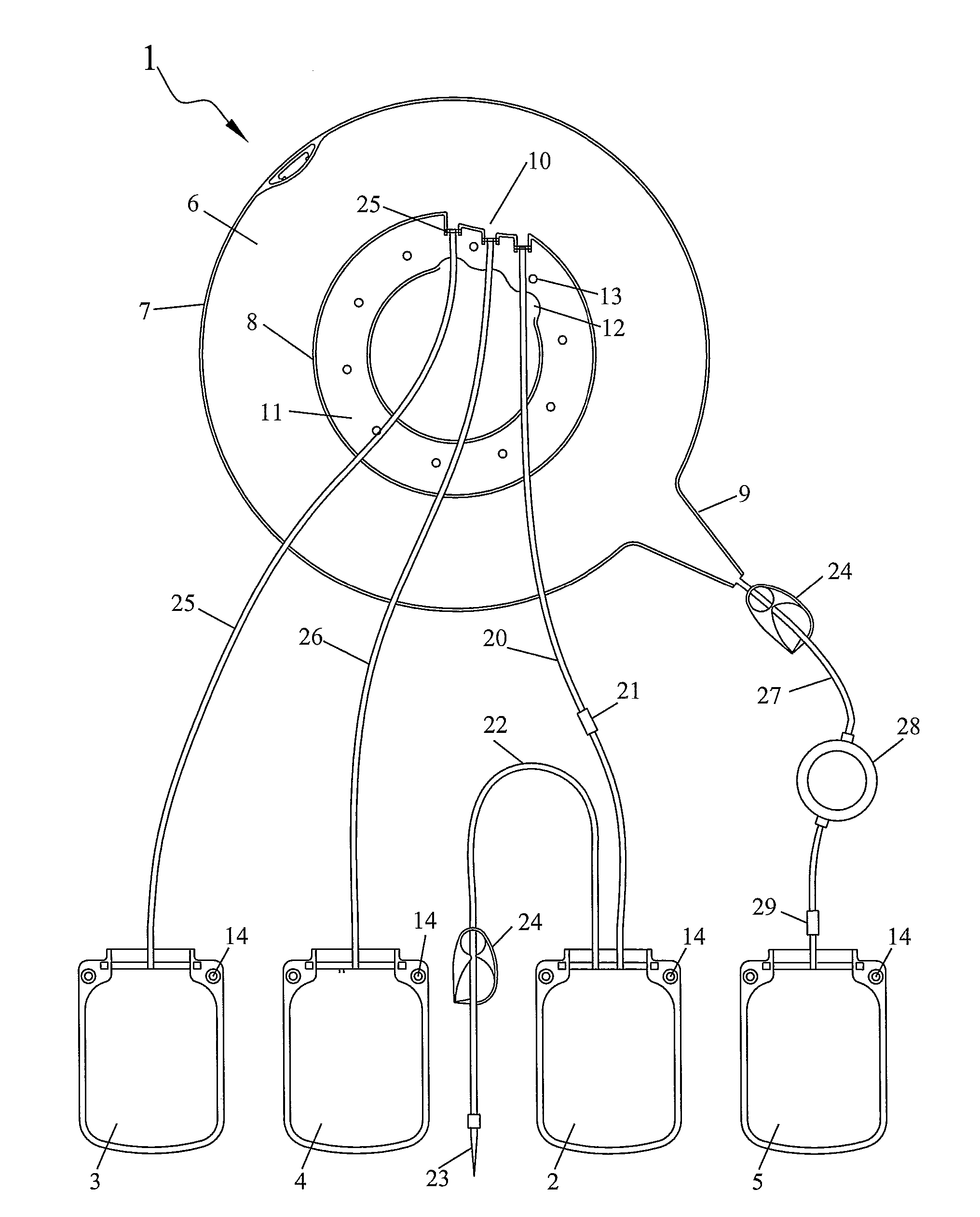
[0015]For the sake of clarity, the invention will be described with respect to a specific use, namely the separation of whole blood into four components, namely a plasma component, a platelet component, a mononuclear cell component, and a red blood cell component. It should be understood however that this specific use is exemplary only. It should also be understood that the principles can be used for collecting at least two components.

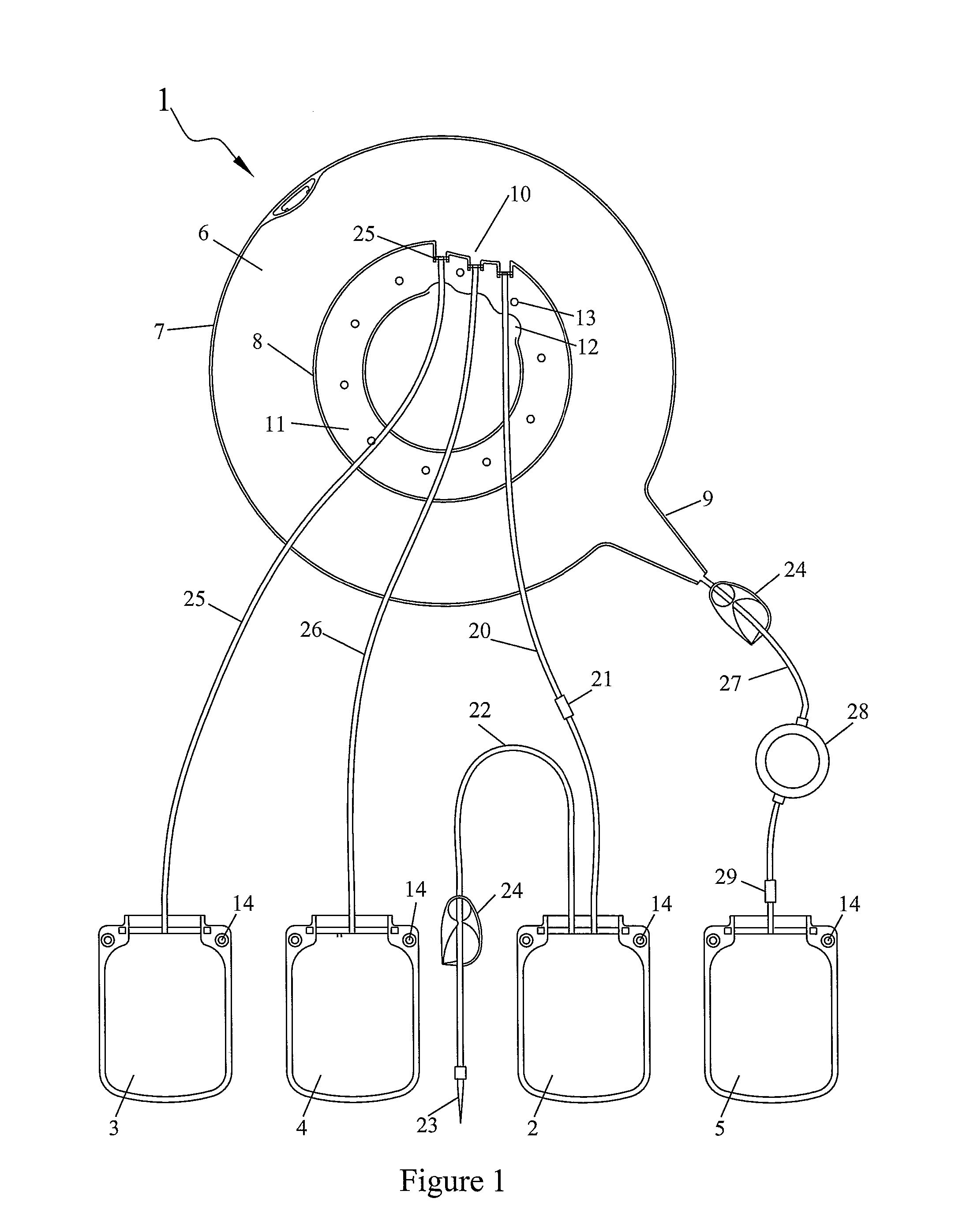
[0016]FIGS. 1 and 2 show an example of a set of bags adapted to the separation of whole blood into a plasma component (essentially comprising plasma), a platelet component (essentially comprising platelets), a mononuclear cell component (comprising monocytes, lymphocytes and some red blood cells) and a red blood cell component (essentially comprising red blood cells and granulocytes). This bag set comprises a flexible separation bag 1 and four flexible transfer bags 2, 3, 4, 5 connected thereto. The separation bag 1 comprises an annular separation cham...


PUM

PropertyMeasurementUnit
Massaaaaaaaaaa
Timeaaaaaaaaaa
Hematocritaaaaaaaaaa

Abstract

A method for controlling a centrifuge blood component separation system for separating components of a blood product, the separation system comprising a centrifuge and a separation bag and at least one transfer bag. The method comprises selecting a nominal hematocrit value such that an actual hematocrit value is expected to be less than said nominal hematocrit; centrifuging a separation bag containing a volume of composite liquid so as to cause the sedimentation of at least a first component and a second component; transferring some of the first component to a first transfer bag; detecting time of passage of a red blood cell interface at a pre-selected location in the separation bag; and adjusting a predicted processing time based on the time of passage of the red blood cell interface.

Description

CROSS REFERENCE TO RELATED APPLICATIONS[0001]This application claims the benefit of U.S. Provisional Application No. 61 / 364,495 filed Jul. 15, 2010.FIELD OF THE INVENTION[0002]The present invention concerns a method for separating a volume of composite biologic liquid or blood product into at least two components. The method optimizes the separation process for minimum separation time in a centrifuge apparatus for separating biologic fluids, such as blood.Background[0003]The apparatus and method of the invention are particularly appropriate for the separation of biological fluids comprising an aqueous component and one or more cellular components. For example, potential uses of the invention include extracting, from a volume of whole blood, a plasma component, a first cellular component including platelets, a second cellular component including mononuclear cells, and a third cellular component including red blood cells and granulocytes.[0004]U.S. patent application Ser. No. 11 / 931,5...

Claims


Application Information

Patent Timeline
IPC IPC(8): B01D21/26
CPCA61M1/3693A61M1/3698B04B2013/006B04B5/0428A61M1/0209A61M1/3696
Inventor HOLMES, BRIAN M.STANTON, BRIDEN RAYVAN WAEG, GEERTLANGLEY, ROBERTLANGLEY, MARY
Owner TERUMO BCT
Features
  • Generate Ideas
  • Intellectual Property
  • Life Sciences
  • Materials
  • Tech Scout
  • Unparalleled Data Quality
  • Higher Quality Content
  • 60% Fewer Hallucinations
Learn More