Joint Cover with Manifold for Duct Leak Detection System

a duct leak detection and joint cover technology, applied in the aerospace field, can solve the problems of hot air leakage from the duct interior to the insulation blanket, and the air flow cannot be sustained,

Active Publication Date: 2012-01-26
SENIOR IP GMBH
View PDF17 Cites 42 Cited by
  • Summary
  • Abstract
  • Description
  • Claims
  • Application Information

AI Technical Summary

Benefits of technology

[0012]With the just-described embodiment of the invention, it has been found, depending upon the distance between the vent hole in the cuff and the sensor wires, that, although there is a steady stream of air being expelled from the vent hole at a temperature sufficient to trip the detector, the air may still have insufficient heat once reaching the sensor wires as the result of its movement between the vent hole and the sensor wires due to a nozzle ejector effect mixing with ambient air around the duct.
[0013]In another embodiment of the invention, a manifold has been added between the cuff and the sensor wires to direct the stream of hot air directly from the vent hole to the sensor wires without the loss of heat to the ambient environment. The design of the preferred embodiment comprises adding a manifold block and a manifold cap installed on top of the cuff and inline with the vent hole in the cuff. The manifold block is designed to route the hot air from a single conduit in the manifold, to a “Y” where the conduit divides into two conduits, which lead directly to the sensor sires. Hot air impingement is accomplished by installing a cap on the manifold block that secures each of the sensor wires in a channel groove. The channel groove in the cap for each sensor wire is designed to align with the outlet of the one of the two conduits running through the manifold from the “Y”. As such, the hot air flow

Problems solved by technology

If sufficient air pressure exists at low volume, air flow velocity cannot be sustained once the volume is quickly

Method used


Image

  • Joint Cover with Manifold for Duct Leak Detection System
  • Joint Cover with Manifold for Duct Leak Detection System
  • Joint Cover with Manifold for Duct Leak Detection System

Examples


Embodiment Construction

[0037]While this invention is susceptible of embodiment in many different forms, there are shown in the drawings and will herein be described in detail, several embodiments with the understanding that the present disclosure should be considered as an exemplification of the principles of the invention and is not intended to limit the invention to the embodiments so illustrated. Further, to the extend that any numerical values or other specifics of materials, etc., are provided herein, they are to be construed as exemplifications of the inventions herein, and the inventions are not to be considered as limited thereby.

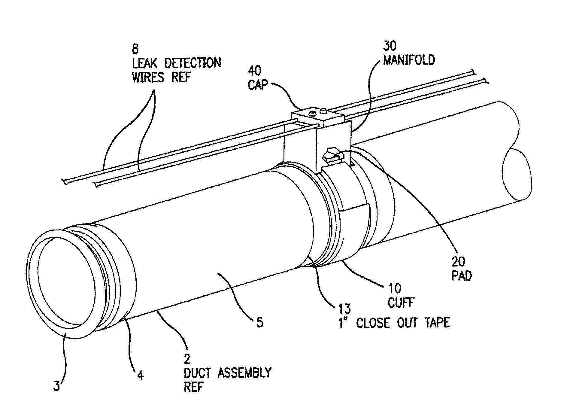
[0038]A typical duct assembly 2 of the type with which the invention is intended to be used is shown in FIG. 6 and comprises an inner metal duct 3, typically composed of steel and 1.00″ to 6.50″ in diameter, covered by insulation blanket 4, and secured by outer insulation shell 5. Insulation blanket 4 and outer insulation shell 5 are composed of materials as previously di...


PUM


Abstract

A leak detector for an insulated duct carrying pressurized hot air comprises a cover secured over a circumferential cut in the insulation of the duct, or over a joint connecting duct sections, thereby creating a reservoir of hot air which has leaked from the duct or joint, a manifold block defining a conduit therein in communication with the hot air reservoir and a cap for securing heat sensitive wires to manifold at the end of the conduit such that the hot air from the hot air reservoir impinges directly on the heat sensitive wires. The leak detector includes flow control mechanisms in the body of the manifold block, to prevent false alarms arising from nominal leakage resulting from ordinary operation of the duct system.

Description

FIELD OF THE INVENTION[0001]This invention is related to the field of aerospace, and, in particular, to modern aircraft which utilize the flow of hot compressed bleed air from the engines for various on-board functions.BACKGROUND OF INVENTION[0002]The present invention relates to the use of ducting systems in aircraft structures. Amongst the prior art, it is well known in the art to use high temperature bleed air from the engines for various on-board purposes in a modern aircraft. Typically, a stream of hot air bled from the engines is used to provide an anti-icing function on the leading edge of the wings and empennage of the aircraft and is also used by the air conditioning units to supply fresh air to the passenger cabin. The bleed air must therefore be transported from the engines to various other areas of the aircraft, and this is typically accomplished utilizing insulated metallic ducts ranging in diameter from 1.00″ to 6.50″ and ranging in length from at least 6″. The air in ...

Claims


Application Information

Patent Timeline
IPC IPC(8): F16L41/00F16L21/02
CPCF16L23/006F16L23/04G01M3/18F16L2201/30G01M3/002F16L59/184Y10T137/5762Y10T137/8326Y10T137/85938
Inventor FERNANDES, LESLIEAMY, ARNAUD
Owner SENIOR IP GMBH
Why Eureka
Try Eureka