Corrosion Protection Method And Corrosion Protection Structure

a corrosion protection and corrosion protection technology, applied in the direction of electrically conductive paints, etc., can solve the problems of galvanic anode consumption problem, difficult to obtain commercial power source, etc., and achieve the effect of preventing contamination, deterioration, and damage of the semiconductor layer, effective corrosion protection treatment, and increasing the degree of freedom

Inactive Publication Date: 2012-01-26
FUJIMORI KOGYO CO LTD +1
View PDF0 Cites 7 Cited by
  • Summary
  • Abstract
  • Description
  • Claims
  • Application Information

AI Technical Summary

Benefits of technology

[0039]According to the first embodiment of the invention, the semiconductor layer does not become wet by rain or the like, and dirt does not adhere thereto. This increases the degree of freedom for the place where the semiconductor layer is installed. In addition, a multitude of electrons can be injected into an object to be protected against corrosion, to thereby perform an effective corrosion protection treatment. Furthermore, the electrons produced by causing the semiconductor layer made of titania (titanium oxide) or the like to receive visible light can be supplied to the steel material in the concrete. As a result, the anode is not consumed, and the electrical corrosion protection is made available even in the place where it is difficult to obtain electricity by a commercial power source.
[0040]According to the second embodiment of the invention, the semiconductor layer does not become wet by rain or the like, and it is possible to prevent contamination, deterioration, and damage of the semiconductor layer. Therefore, the degree of freedom for the place where the semiconductor layer is installed is high. In the case of protecting the steel material or the like buried in the mortar or concrete against corrosion, the semiconductor layer together with the layer of the mortar or concrete over which the steel material or the like is present is also protected by the film. Therefore, it is possible to suppress the permeation of deterioration factors for mortar or concrete such as ion chloride or carbon dioxide into the mortar or concrete around the steel material or the like. This suppresses deterioration of the mortar or concrete.
[0041]According to the third embodiment of the invention, it is possible to install the semiconductor layer even in the shade, and provide the high degree of freedom in construction work for corrosion protection.
[0042]According to the fourth embodiment of the invention, it is easy to undertake corrosion protection work of the steel material buried in the mortar or concrete, and it is possible to make it possible to significantly reduce the labor required for installing the anode.
[0043]According to the fifth embodiment of the invention, even if the object to be protected against corrosion is made of metal coated with a coating layer of a coating agent, sticking the electrolytic layer having glutinousness or adhesiveness on the coating makes corrosion protection possible.
[0044]According to the sixth embodiment of the invention, the semiconductor layer does not become wet by rain or the like, and dirt does not adhere thereto. Therefore, the degree of freedom for the place where the semiconductor layer is installed is high. Furthermore, even if the amount of emitted electrons is low, an effective injection of the electrons into the object to be protected against corrosion makes it possible to perform effective corrosion protection.

Problems solved by technology

However, the external power source has problems in that the maintenance management of power source and the management of corrosion protection current are required, and in that obtaining a commercial power source is sometimes difficult.
Furthermore, the galvanic anode has a problem of being consumed over time.

Method used


Image

  • Corrosion Protection Method And Corrosion Protection Structure
  • Corrosion Protection Method And Corrosion Protection Structure
  • Corrosion Protection Method And Corrosion Protection Structure

Examples


examples

[0099]Hereunder is a specific description of the present invention with reference to examples.

[Corrosion Protection Structure of Example 1]

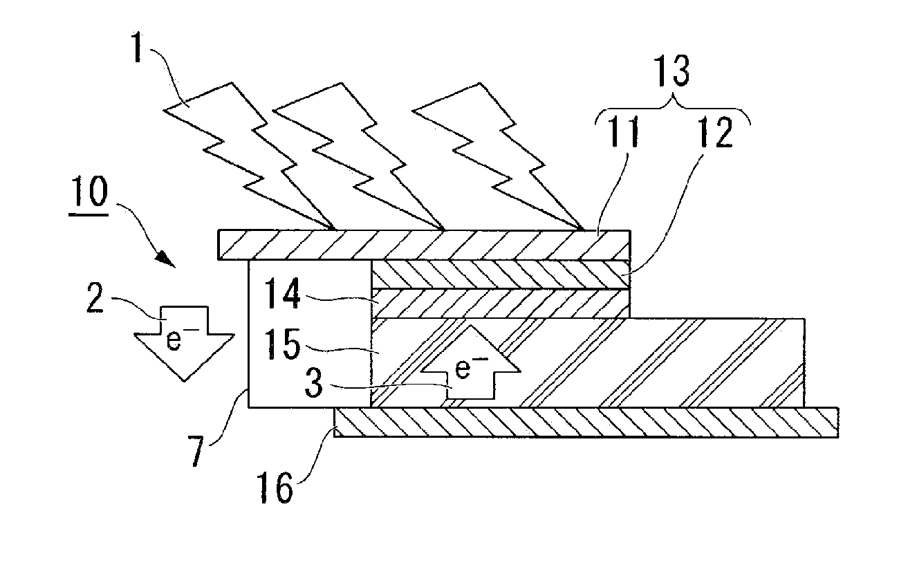
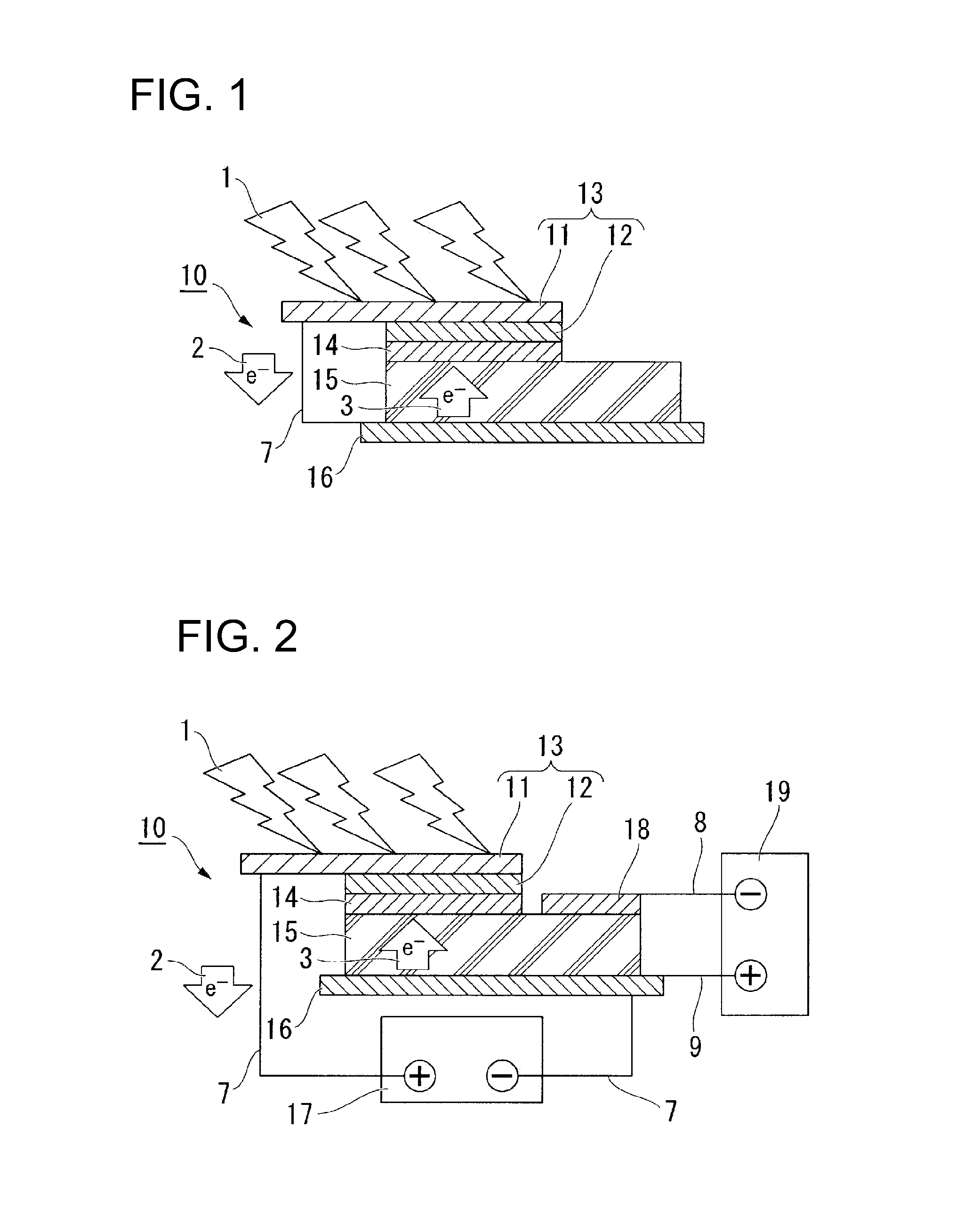
[0100]ITO was vacuum-deposited on a transparent PEN film with a thickness of 200 μm to prepare a supporting member 11 with a dimension of 50×35 mm with which electrical conductivity of a surface resistance: 10Ω / □ (square) was provided.

[0101]On the ITO-deposited surface of the PEN film, a brookite-type titanium oxide paste (C-paste manufactured by SHOWA DENKO K. K.) as a semiconductor layer 12 was applied and dried in a size of 40×25 mm to provide a titanium oxide layer 12 with a thickness of 10 μm. Thus, an electron supplier 13 was obtained.

[0102]As an object to be protected against corrosion 16, a steel material (SS400 material) with a dimension of 60 mm×70 mm×2 mm was used which had been blasted with alumina. To simulate a steel material 16 in a concrete layer 15, a cement paste was applied on the steel material 16 and a mortar plate with a siz...


PUM

PropertyMeasurementUnit
wavelengthaaaaaaaaaa
wavelengthsaaaaaaaaaa

Abstract

A semiconductor layer (12) is caused to receive electromagnetic waves (1) to emit electrons; the emitted electrons are collected and supplied to an object to be protected against corrosion; and the electrons (3) are returned from the object to be protected against corrosion (16), to which the electrons (2) are supplied, to the semiconductor layer (12) via an electrolytic layer (14), to thereby cause an electric current to flow to the object to be protected against corrosion (16) to make a potential of the object to be protected against corrosion (16) low. In a corrosion protection structure (10), an electron supplier (13) is electrically connected to a object to be protected against corrosion (16), to thereby provide corrosion protection, the electron supplier (13) being made of a semiconductor layer (12) formed on a supporting member (11) that is capable of transmitting electromagnetic waves and has electrical conductivity. In addition, the electron supplier (13) is electrically connected to an object to be protected against corrosion (16) via an electrolytic layer (14) that is at least in contact with the semiconductor layer (12). According to the present invention, even if an object to be protected against corrosion is coated with a coating layer such as a rebar in concrete, it is possible to provide a corrosion protection method and a corrosion protection structure that can obtain a sufficient corrosion protection effect.

Description

TECHNICAL FIELD[0001]The present invention relates to a cathodic corrosion protection method and a corrosion protection structure thereby. More particularly, the present invention relates to a corrosion protection method and a corrosion protection structure in the case where objects to be protected against corrosion are coated with a coating layer such as rebars in the concrete.[0002]Priority is claimed on Japanese Patent Application No. 2009-8068, filed on Jan. 16, 2009, the content of which is incorporated herein by reference.BACKGROUND ART[0003]There are construction techniques in which an electric current is caused to flow from an electrode (for example, an anode) installed on the surface of the concrete to steel materials such as rebars in the concrete. This changes the potential of the steel materials to a level that does not produce corrosion, to thereby prevent the progress of corrosion. Among these, electrical protection techniques are known.[0004]In conventional electrical...

Claims


Application Information

Patent Timeline
Patent Type & Authority Applications(United States)
IPC IPC(8): C23F13/00
CPCC09D5/24C23F2201/02C23F13/06C23F13/02C23F13/20C23F13/00C23F15/00
Inventor YAMAMOTO, SHIROUKIMURA, TETSUSHIKOGURE, HIDEO
Owner FUJIMORI KOGYO CO LTD
Why Eureka
Try Eureka