Dual Polarized Reflector Antenna Assembly

a dual-polarized reflector and antenna technology, applied in the direction of antennas, antenna details, electrical equipment, etc., can solve the problems of depolarization becoming an additional factor, reducing the electrical performance of each signal, and affecting the overall performance of the communication link

Active Publication Date: 2012-01-26
COMMSCOPE TECH LLC
View PDF2 Cites 8 Cited by
  • Summary
  • Abstract
  • Description
  • Claims
  • Application Information

AI Technical Summary

Benefits of technology

[0031]The inventors have invented a dual polarized reflector antenna assembly wherein the OMT / interconnecting waveguide elements, mountable upon a rear side of the reflector / reflector feed hub, may enable transceiver mounting proximate the backside of the reflector with improved electrical performance. Further, the modular features of the OMT / waveguide elements may also enable easy exchange / configuration for operation at varied operating frequencies and / or with desired electrical performance trade-off characteristics.
[0055]Each of the OMT / feed assembly 12 embodiments may be exchanged for one another using a common reflector dish 6, feed hub 8 and transceiver support bracket 4, thereby easy configuration for optimized operation across the wide range of typical microwave frequencies is obtained without requiring separate design, manufacture and inventory of a plurality of frequency specific reflector antenna configurations. Further, easy onsite upgrade of existing single polarity reflector antenna assembly installations to dual polarized configuration is enabled, because the feed hub 8 and associated subreflector / feed assemblies need not be disturbed, including the alignment with and / or seals between the subreflector / feed, feed hub 8 and / or reflector dish 6.Table of Parts2dual polarized reflector antenna assembly4transceiver support bracket6reflector dish8feed hub10reflector antenna12OMT / feed assembly14 feed port16 proximal end18 distal end22 circular to square waveguide transition24 square waveguide module26 OMT28 polarization adapter30 square waveguide31 coupling position32 trough portion34 side wall36lid portion38 key feature40 fastener42 output port44 rectangular waveguide46 OMT half48 square waveguide input port49 OMT intersection50 feedport adapter52 circular waveguide

Problems solved by technology

However, electrical performance with respect to each signal may be reduced, due to signal separation requirements and / or interference between each of the signals.
If the XPD of a dual polarized antenna assembly is degraded, the cross-polar interference cancellation (XPIC) will be poor, which means that the orthogonal channels will interfere with each other, degrading the overall communications link performance.
However, if the OMT / signal paths are physically large, depolarization becomes an additional factor, as the signal energy has to travel an increased distance between the radio port and the feed port.
The internal signal surface of the WO 2007 / 088183 OMT includes an intricate projecting island septum polarizer feature that may be difficult to cost effectively machine with precision due to OMT element sectioning aligned normal to the signal path.
Because the OMT is also the feed hub of the reflector antenna, it may be difficult to harmonize components between various reflector antenna configurations and / or apply alternative OMT configurations to existing installations, for example in a field conversion / upgrade of existing reflector antenna assemblies from single to dual polarized operation.
Each additional 90 degree signal path change complicates manufacture, extends the overall signal path and introduces an additional opportunity for IPI and / or depolarization degradation of the signals.

Method used


Image

  • Dual Polarized Reflector Antenna Assembly
  • Dual Polarized Reflector Antenna Assembly
  • Dual Polarized Reflector Antenna Assembly

Examples


first embodiment

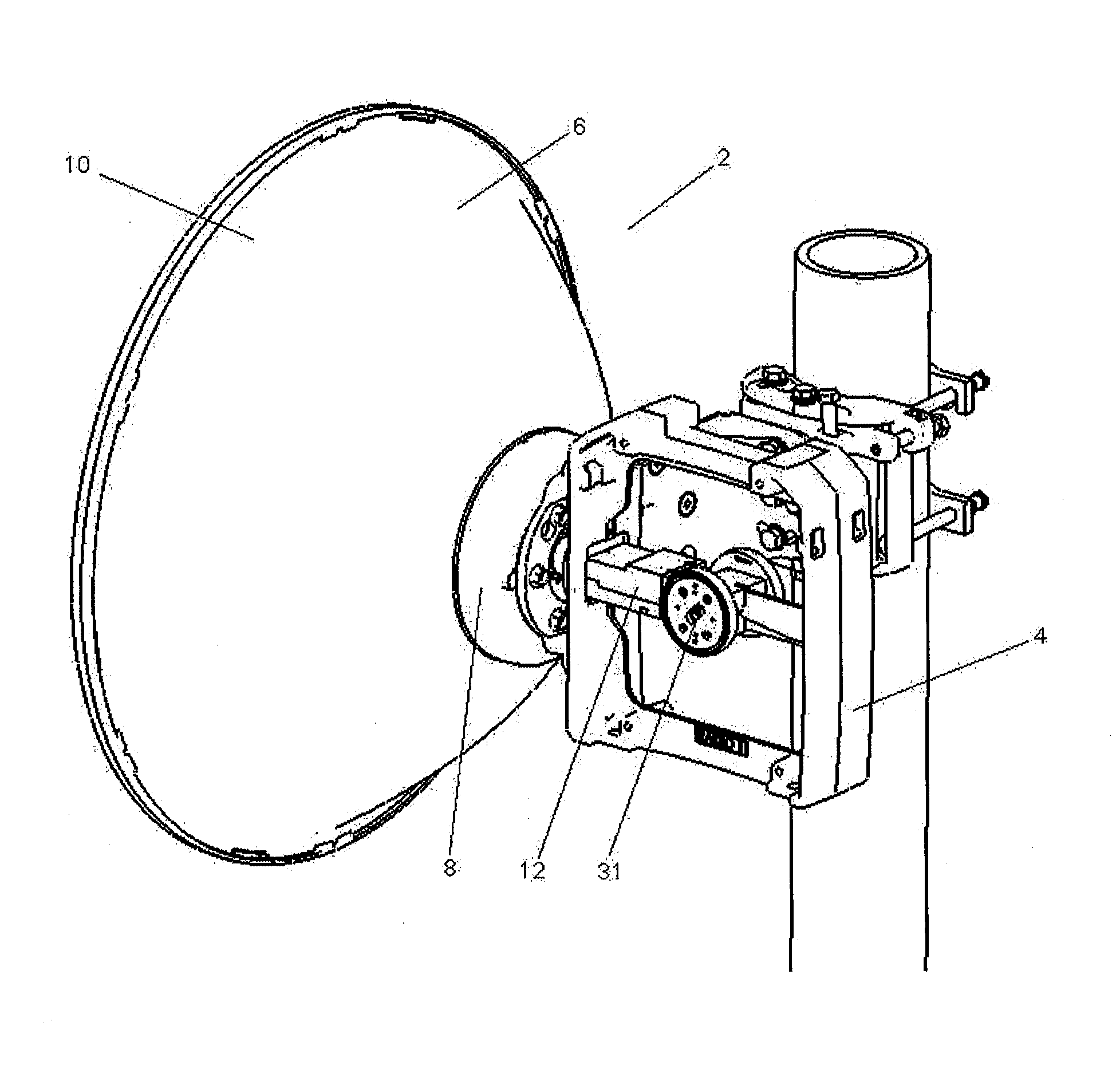
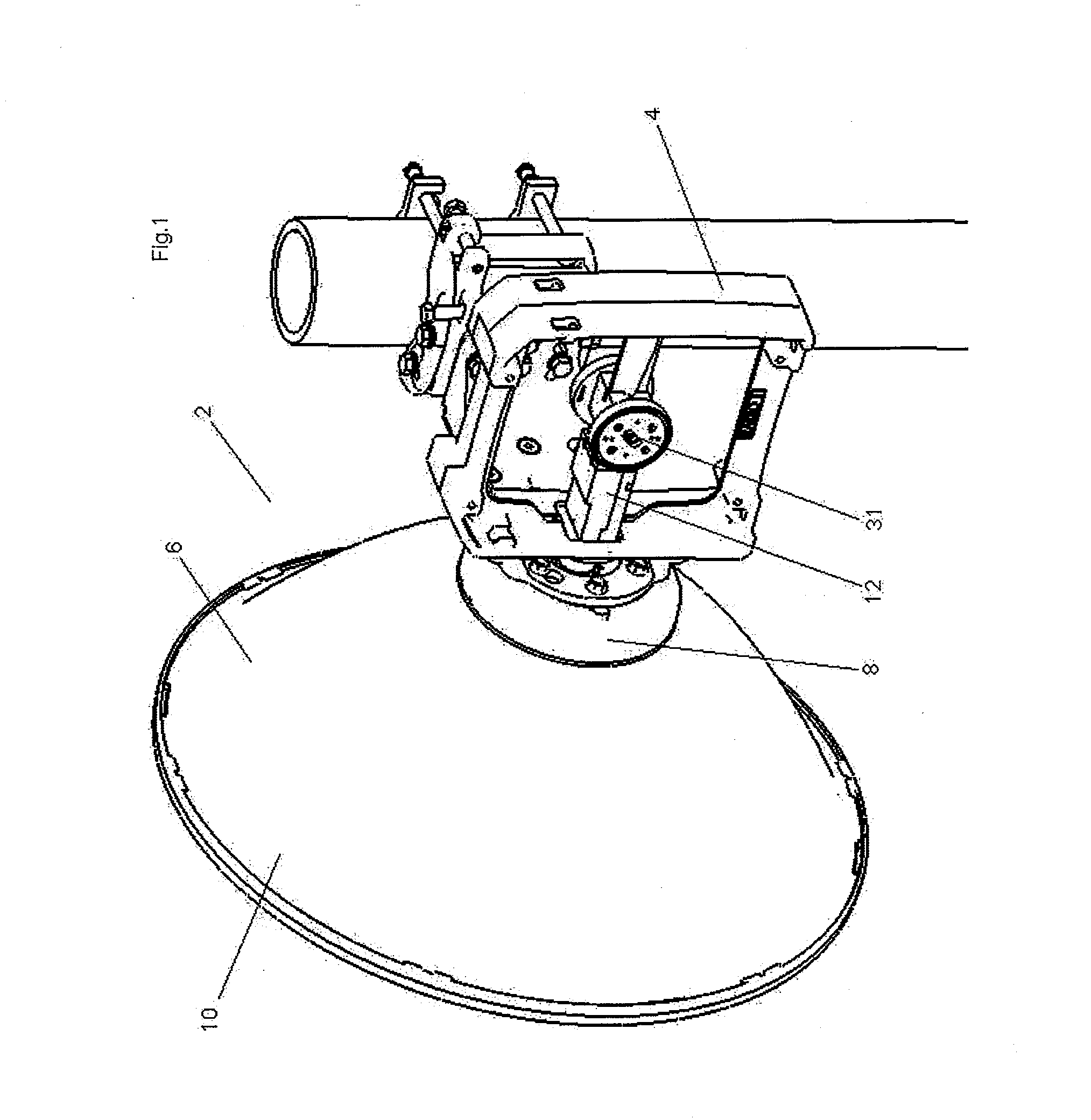
[0032]In a dual polarized reflector antenna assembly 2, as shown in FIGS. 1 and 2, with transceivers (alternatively separate receivers and / or transmitters) removed for clarity, a transceiver support bracket 4 is coupled proximate the back side of a reflector dish 6, secured to a feed hub 8 of the reflector antenna 10. An OMT / feed assembly 12 may be coupled, for example, to a feed port 14 of the feed hub 8 at a proximal end 16 and supported by the transceiver support bracket 4 at a distal end 18.

[0033]One skilled in the art will appreciate that proximal end 16 and distal end 18 are end designations provided for ease of explanation of element orientation and / or interconnection. Each of the elements within an assembly also has a proximal end 16 and a distal end 18, that is, the ends of the element facing the proximal end 16 or distal end 18, respectively, of the associated assembly.

[0034]As best shown in FIG. 3, the OMT / feed assembly 12 includes a circular to square waveguide transitio...

second embodiment

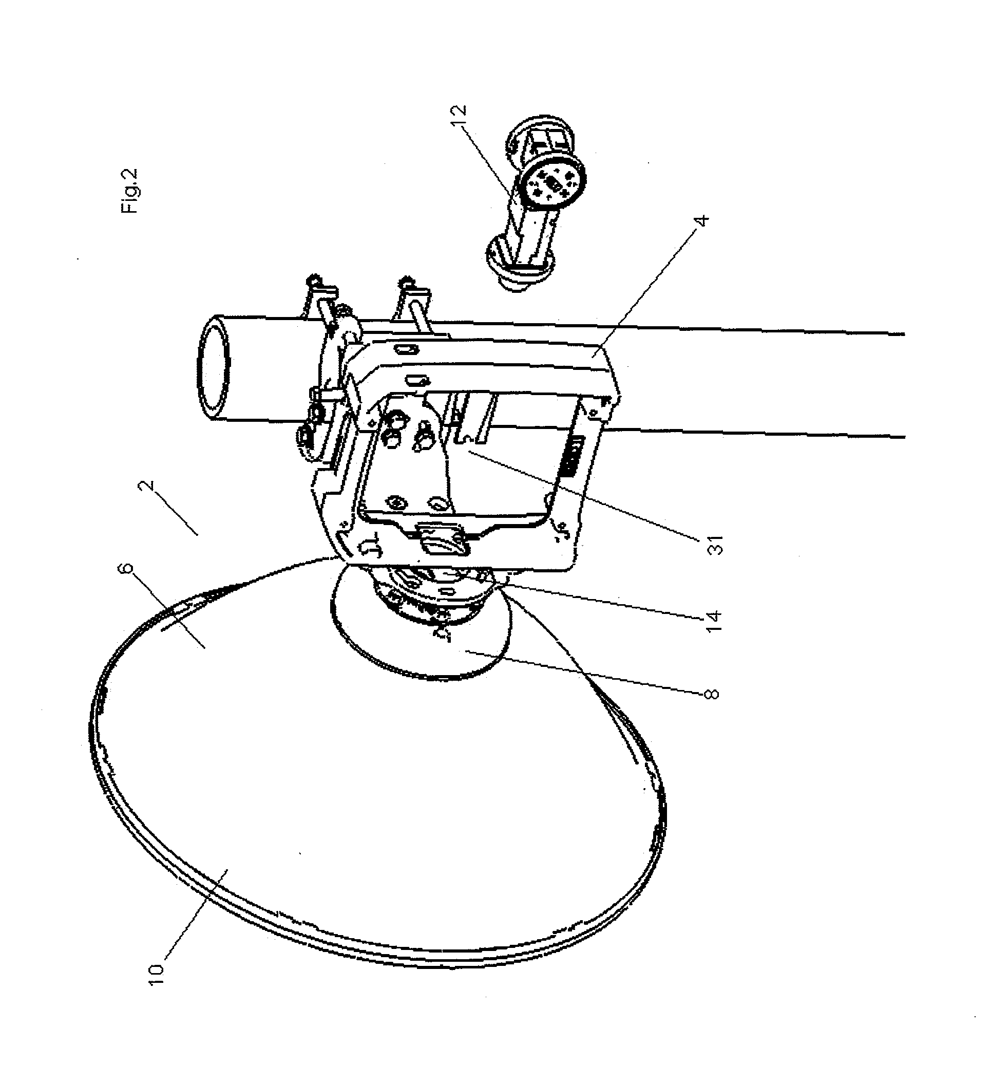
[0043]In a dual polarized reflector antenna assembly 2, as shown in FIGS. 8 and 9, with the transceivers (alternatively separate receivers and / or transmitters) removed for clarity, a transceiver support bracket 4 is coupled proximate the back side of a reflector dish 6, secured to a feed hub 8 of the reflector antenna 10. An OMT / feed assembly 12 is coupled to a feed port 14 of the feed hub 8 at a proximal end 16 and supported by the transceiver support bracket 4 at a distal end 18.

[0044]As best shown in FIG. 10, the OMT / feed assembly 12 includes a circular to square waveguide transition 22, an OMT 26 and polarization adapters 28 coupled in-line to form a signal path from the feed port 14 of the feed hub 8 to input ports of the transceivers.

[0045]As shown in FIGS. 11 and 12, the OMT 26 may be formed from two OMT halves 46 also mating together via key features 38 such as pins and sockets and / or a plurality of fasteners 40 such as screws or the like. The OMT 26 separates and transition...

third embodiment

[0049]In a dual polarized reflector antenna assembly 2, as shown in FIGS. 13 and 14, transceivers (alternatively separate receivers and / or transmitters) removed for clarity, a transceiver support bracket 4 is coupled proximate the back side of a reflector dish 6, secured to a feed hub 8 of the reflector antenna 10. An OMT / feed assembly 12 is coupled to a feed port 14 of the feed hub 8 at a proximal end 16 and supported by the transceiver support bracket 4 at a distal end 18.

[0050]As best shown in FIG. 15, the OMT / feed assembly 12 includes a feed port adapter 50, a circular waveguide 52, circular to square waveguide transition 22, an OMT 26 and polarization adapters 28 coupled in-line to form a signal path from the feed port 14 of the feed hub 8 to input ports of the transceivers.

[0051]As shown in FIGS. 16 and 17, the OMT 26 may be formed from two OMT halves 46 also mating together via key features 38 such as pins and sockets and / or a plurality of fasteners 40 such as screws or the l...


PUM


Abstract

A dual polarized reflector antenna assembly, provided with a reflector dish coupled to a feed hub with a feed port there through; a transceiver support bracket coupled to a backside of the feed hub; a circular to square waveguide transition coupled to the feed port; a square waveguide coupled to the circular to square waveguide transition; an OMT coupled to the square waveguide; the OMT provided with an OMT intersection between a square waveguide and a pair of rectangular waveguides oriented at ninety degrees to one another, an output port of each rectangular waveguide arranged normal to a longitudinal axis of the dual polarized reflector antenna assembly. Alternatively, a circular waveguide may be applied between the feed port and the circular to square waveguide transition, eliminating the square waveguide, or the rectangular waveguides may be extended longitudinally, also eliminating the square waveguide.

Description

BACKGROUND[0001]1. Field of the Invention[0002]This invention relates to reflector antennas. More particularly, the invention relates to a dual polarized reflector antenna assembly with signal path and Ortho Mode Transducer (OMT) configurations providing improved electrical performance.[0003]2. Description of Related Art[0004]Dual polarized microwave communications links utilize a pair of signals, each using different polarities, thus enabling a significant link capacity increase compared to single signal / dual polarity communications links. However, electrical performance with respect to each signal may be reduced, due to signal separation requirements and / or interference between each of the signals. With the increasing demand for link capacity in terrestrial communications systems, especially in limited RF spectrum environments, the use of dual polarized communications links is increasing.[0005]Traditional terrestrial communications reflector antennas for use with single signal / dua...

Claims


Application Information

Patent Timeline
IPC IPC(8): H01Q19/17H01Q13/00H01Q19/02
CPCH01P1/161H01Q19/12H01Q1/1228
Inventor SYED, JUNAIDTAPPIN, KEITHTASKER, ALLANMACLEOD, GARYZHU, WENJIECHEN, HAIDONG
Owner COMMSCOPE TECH LLC
Why Eureka
Try Eureka