[0014]According to an aspect of the invention, the combined and coordinated use of relatively high
dielectric strength insulating mediums and conductive or semi-conductive coatings effectively reduce the localized electrical field stress of the conductive objects used to secure the earthing
electrode.
[0015]According to another aspect of the invention, a non-conductive, removable covering and cap with a conductive or semi-conductive internal
coating is used for one or more of the following purposes: 1) electrically shielding the components within its boundaries, 2) bringing the covering's internal surface and the components within its boundaries to an
equipotential state for the purpose of lowering field stress below what would be expected if the
internal object(s) were left exposed in an unshielded state, 3) providing a dielectric barrier between the enclosed receptor connection
assembly and neighboring conductive objects, and 4) serving as a boundary for a dielectric medium used to fill any internal voids for the purpose of enhanced
electrical isolation.
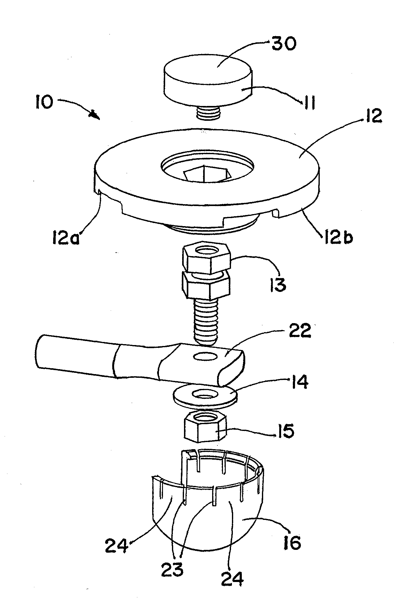
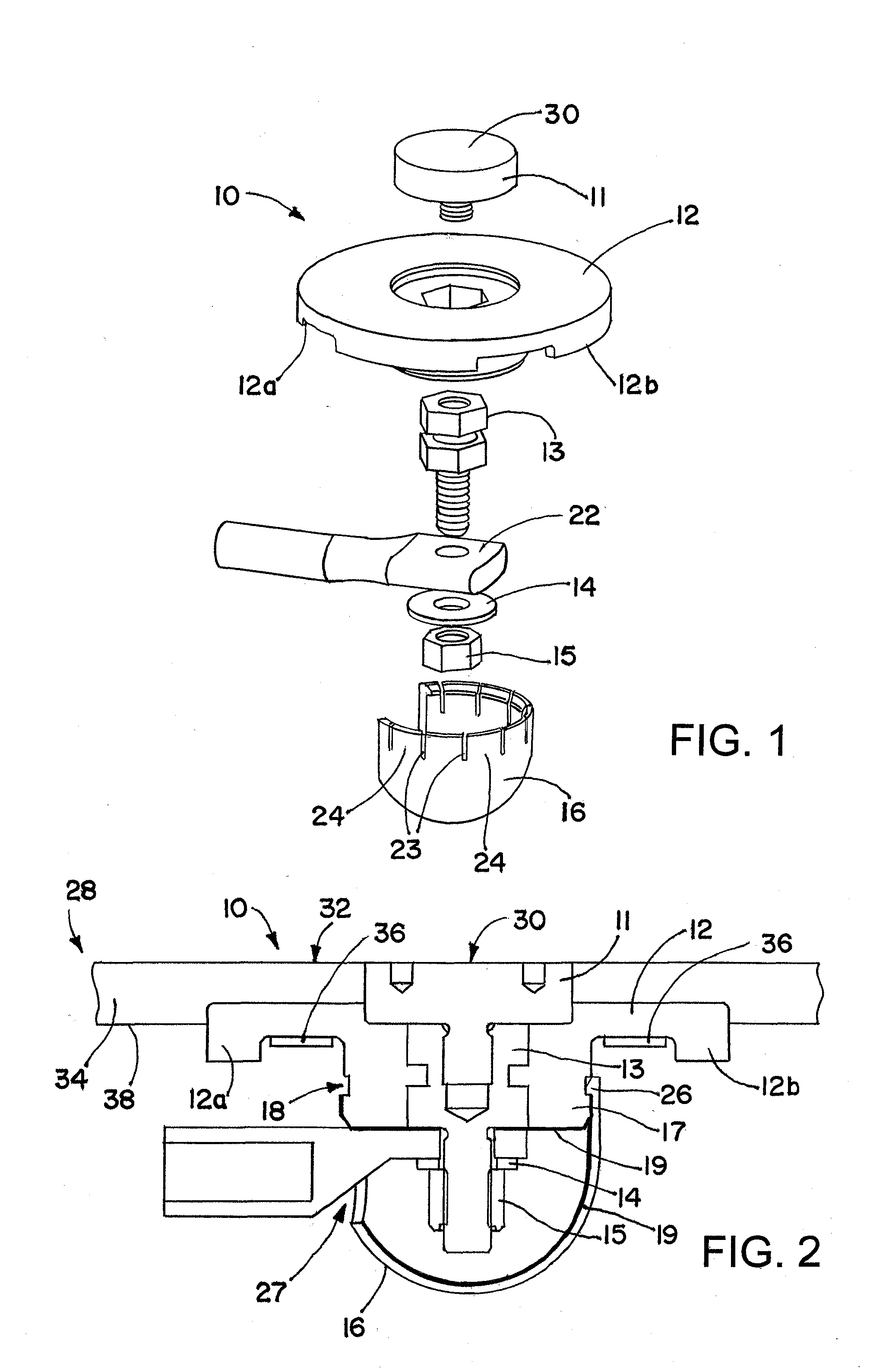
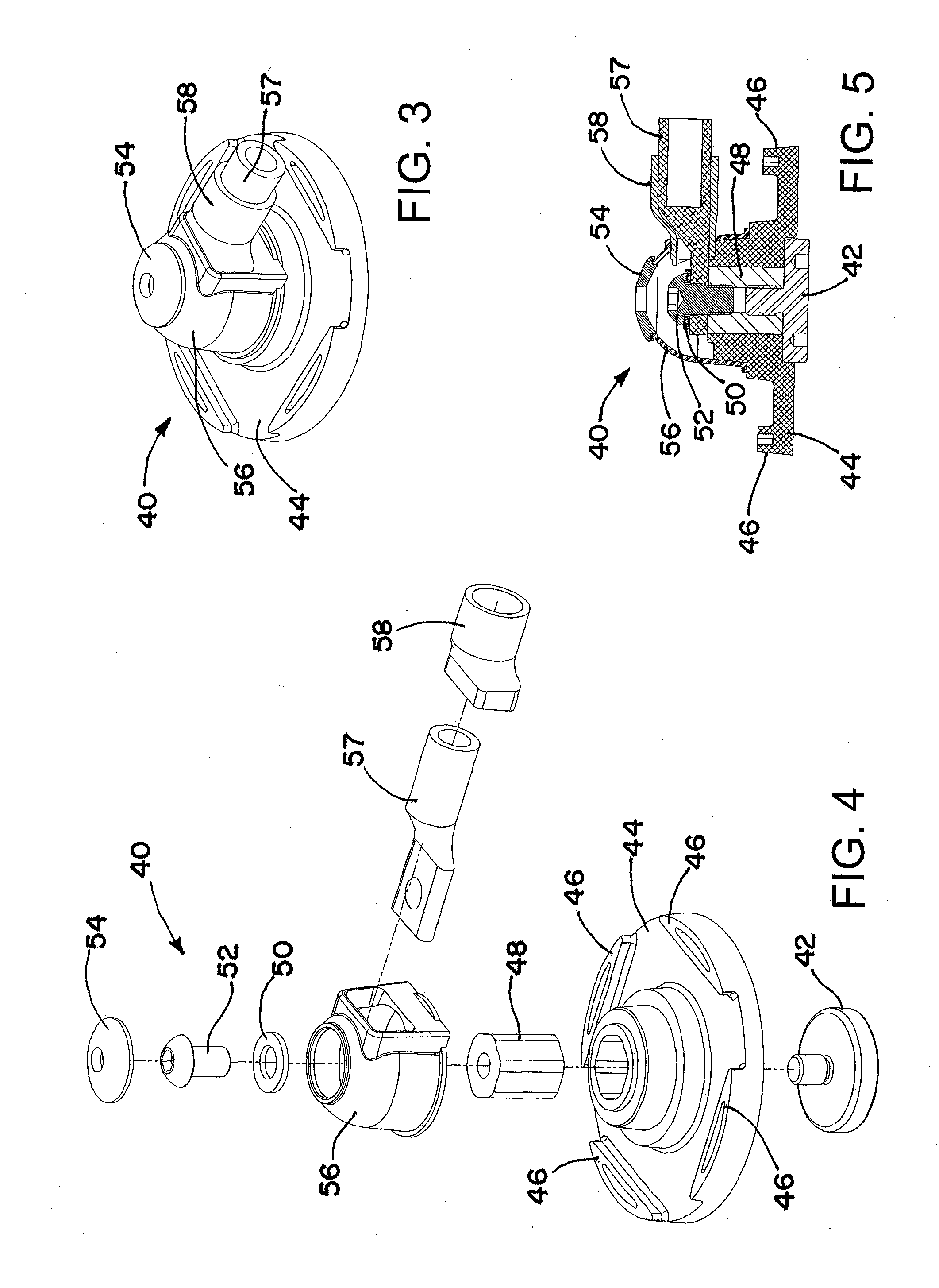
[0019]According to a still further aspect of the invention, a receptor assembly includes one or more of the following: a receptor disk (also known as a puck or plug); an insulating disk or receptor block insulator, which may have tabs; a receptor block; a
washer; a
threaded fastener; an insulating cover; and a
fastener cap. An opening in the insulating cover may receive a compression lug and / or a
grommet (which may be around part of the compression lug). A shaft of the
threaded fastener may be passed through the
washer, and / or may engage the receptor block, securing the compression lug to the receptor block. A threaded stud of the receptor disk may threadedly engage an opposite end of the receptor block, thereby electrically connecting the receptor disk to the compression lug. The receptor block may be secured in a central opening in the receptor block insulator. A conductive or semi-
conductive coating may be provided on surfaces of the receptor block, the receptor block insulator, the insulating cover, and / or the
fastener cap for example to provide conductive material at least partially surrounding the end of the compression lug that is within the insulating cover. The receptor block assembly may be secured relative to a hole or cavity in a
turbine blade using bond paste on the underside and around the perimeter and fiberglass strips and / or loose rovings that are laid across a surface of the receptor block insulator and an inner surface of the wall of the wind
turbine blade; with the receptor block assembly so secured the tabs may aid in preventing rotation or other dislodgment of the receptor assembly, and / or a top surface of the receptor may be substantially flush with an outer surface of the turbine blade. The
fastener cap may be mechanically coupled to the insulating cover, enveloping at least part of a head of the
threaded fastener.
[0025]According to another aspect of the invention, a method of installing a receptor assembly on a device includes one or more of the following: applying a mold release compound to an exterior of an installation plug; threading a
set screw into the installation plug; applying an
adhesive masking tape to the perimeter of the face of the installation plug that comes into contact with the mold wall (this serves multiple purposes: a) securing the plug to the mold wall at a defined location; b) preventing vacuum drawn resin from entering the plug threaded hole from the underside; c) preventing resin from curing between the exterior face of the plug and the blade wall, which would effectively encapsulate the plug and prevent its removal); constructing a device, such as a wind turbine blade wall, around the plug; covering the internal face of the installation plug with
adhesive masking tape, which seals the other end of the plug threaded hole from resin ingress; sealing the mold and infusing the device with resin; curing the resin; removing the
adhesive masking tape from the internal face of the installation plug to
expose the plug threaded hole; inserting the alignment pin into the plug threaded hole of the installation plug;
coating the underside perimeter of the receptor block insulator with bonding paste; placing a receptor block assembly onto the alignment pin; rotating the receptor block assembly into an orientation conducive to connecting the conductor lead (
branch conductor) to the root down conductor at the pre-defined orientation; surrounding the perimeter of the receptor block insulator with bond paste filling any gaps between the underside of the receptor block insulator and the device (inner blade wall); adhering fiberglass strips and / or loose rovings around the perimeter of the central circular boss of the receptor block insulator, extending from the internal face of the receptor block assembly onto the internal blade wall; curing the fiberglas strips or loose rovings; closing the blade; removing the device from the mold; removing the adhesive masking tape from the external face of the installation plug; rotating the
set screw within the installation plug threaded hole, wherein the rotating includes 1) pushing the alignment pin to bottom out against a receptor screw of the receptor assembly that is in the receptor, and 2) after the alignment pin is bottomed out, ejecting the plug, thereby leaving a receptor disk cavity in the device; and inserting a receptor into the receptor disk cavity, wherein the inserting includes threadedly engaging the receptor with the receptor block threaded hole.


