Receptor for wind turbine blade lightning protection

a technology for wind turbine blades and receptors, which is applied in the direction of wind energy generation, liquid fuel engine components, and connection to earth, can solve the problems of damage or fatigue, current receptors typically do not insulate internal receptor components or connections, and current practices fail to adequately deter the initiation of upward leaders from conductive elements, etc., to achieve high dielectric strength and reduce the localized electrical field stress of conductive objects.

Inactive Publication Date: 2014-05-20
ERICO INT
View PDF47 Cites 10 Cited by
  • Summary
  • Abstract
  • Description
  • Claims
  • Application Information

AI Technical Summary

Benefits of technology

[0014]According to an aspect of the invention, the combined and coordinated use of relatively high dielectric strength insulating mediums and conductive or semi-conductive coatings effectively reduce the localized electrical field stress of the conductive objects used to secure the earthing electrode.
[0015]According to another aspect of the invention, a non-conductive, removable covering and cap with a conductive or semi-conductive internal coating is used for one or more of the following purposes: 1) electrically shielding the components within its boundaries, 2) bringing the covering's internal surface and the components within its boundaries to an equipotential state for the purpose of lowering field stress below what would be expected if the internal object(s) were left exposed in an unshielded state, 3) providing a dielectric barrier between the enclosed receptor connection assembly and neighboring conductive objects, and 4) serving as a boundary for a dielectric medium used to fill any internal voids for the purpose of enhanced electrical isolation.
[0019]According to a still further aspect of the invention, a receptor assembly includes one or more of the following: a receptor disk (also known as a puck or plug); an insulating disk or receptor block insulator, which may have tabs; a receptor block; a washer; a threaded fastener; an insulating cover; and a fastener cap. An opening in the insulating cover may receive a compression lug and / or a grommet (which may be around part of the compression lug). A shaft of the threaded fastener may be passed through the washer, and / or may engage the receptor block, securing the compression lug to the receptor block. A threaded stud of the receptor disk may threadedly engage an opposite end of the receptor block, thereby electrically connecting the receptor disk to the compression lug. The receptor block may be secured in a central opening in the receptor block insulator. A conductive or semi-conductive coating may be provided on surfaces of the receptor block, the receptor block insulator, the insulating cover, and / or the fastener cap for example to provide conductive material at least partially surrounding the end of the compression lug that is within the insulating cover. The receptor block assembly may be secured relative to a hole or cavity in a turbine blade using bond paste on the underside and around the perimeter and fiberglass strips and / or loose rovings that are laid across a surface of the receptor block insulator and an inner surface of the wall of the wind turbine blade; with the receptor block assembly so secured the tabs may aid in preventing rotation or other dislodgment of the receptor assembly, and / or a top surface of the receptor may be substantially flush with an outer surface of the turbine blade. The fastener cap may be mechanically coupled to the insulating cover, enveloping at least part of a head of the threaded fastener.
[0025]According to another aspect of the invention, a method of installing a receptor assembly on a device includes one or more of the following: applying a mold release compound to an exterior of an installation plug; threading a set screw into the installation plug; applying an adhesive masking tape to the perimeter of the face of the installation plug that comes into contact with the mold wall (this serves multiple purposes: a) securing the plug to the mold wall at a defined location; b) preventing vacuum drawn resin from entering the plug threaded hole from the underside; c) preventing resin from curing between the exterior face of the plug and the blade wall, which would effectively encapsulate the plug and prevent its removal); constructing a device, such as a wind turbine blade wall, around the plug; covering the internal face of the installation plug with adhesive masking tape, which seals the other end of the plug threaded hole from resin ingress; sealing the mold and infusing the device with resin; curing the resin; removing the adhesive masking tape from the internal face of the installation plug to expose the plug threaded hole; inserting the alignment pin into the plug threaded hole of the installation plug; coating the underside perimeter of the receptor block insulator with bonding paste; placing a receptor block assembly onto the alignment pin; rotating the receptor block assembly into an orientation conducive to connecting the conductor lead (branch conductor) to the root down conductor at the pre-defined orientation; surrounding the perimeter of the receptor block insulator with bond paste filling any gaps between the underside of the receptor block insulator and the device (inner blade wall); adhering fiberglass strips and / or loose rovings around the perimeter of the central circular boss of the receptor block insulator, extending from the internal face of the receptor block assembly onto the internal blade wall; curing the fiberglas strips or loose rovings; closing the blade; removing the device from the mold; removing the adhesive masking tape from the external face of the installation plug; rotating the set screw within the installation plug threaded hole, wherein the rotating includes 1) pushing the alignment pin to bottom out against a receptor screw of the receptor assembly that is in the receptor, and 2) after the alignment pin is bottomed out, ejecting the plug, thereby leaving a receptor disk cavity in the device; and inserting a receptor into the receptor disk cavity, wherein the inserting includes threadedly engaging the receptor with the receptor block threaded hole.

Problems solved by technology

Lightning damage to wind turbine blades can occur in several ways: 1) an upward leader originating from an object within the blade instead of the external face of a receptor; 2) “tracking” or shift in the attachment point during the lightning conduction phase; 3) side-flash or arcing within the blade during the lightning conduction phase; and / or 4) damage or fatigue has also been reported due to streamer currents in the pre-lightning attachment phase.
Lightning damage to installed blades has led some in the industry to draw the conclusion that current practices fail to adequately deter the initiation of upward leaders from conductive elements of the receptor, or more specifically, the internally mounted lightning protection system components.
Current receptors typically do not insulate the internal receptor components or connections with anything other than bonding paste and / or the resin that is used to bond the glass fiber.
Insulating the receptor block and cable connections by surrounding or encapsulating the conductive components in a relatively high dielectric strength medium may not be sufficient to prevent these internal components from generating upward leaders.

Method used


Image

  • Receptor for wind turbine blade lightning protection
  • Receptor for wind turbine blade lightning protection
  • Receptor for wind turbine blade lightning protection

Examples


Embodiment Construction

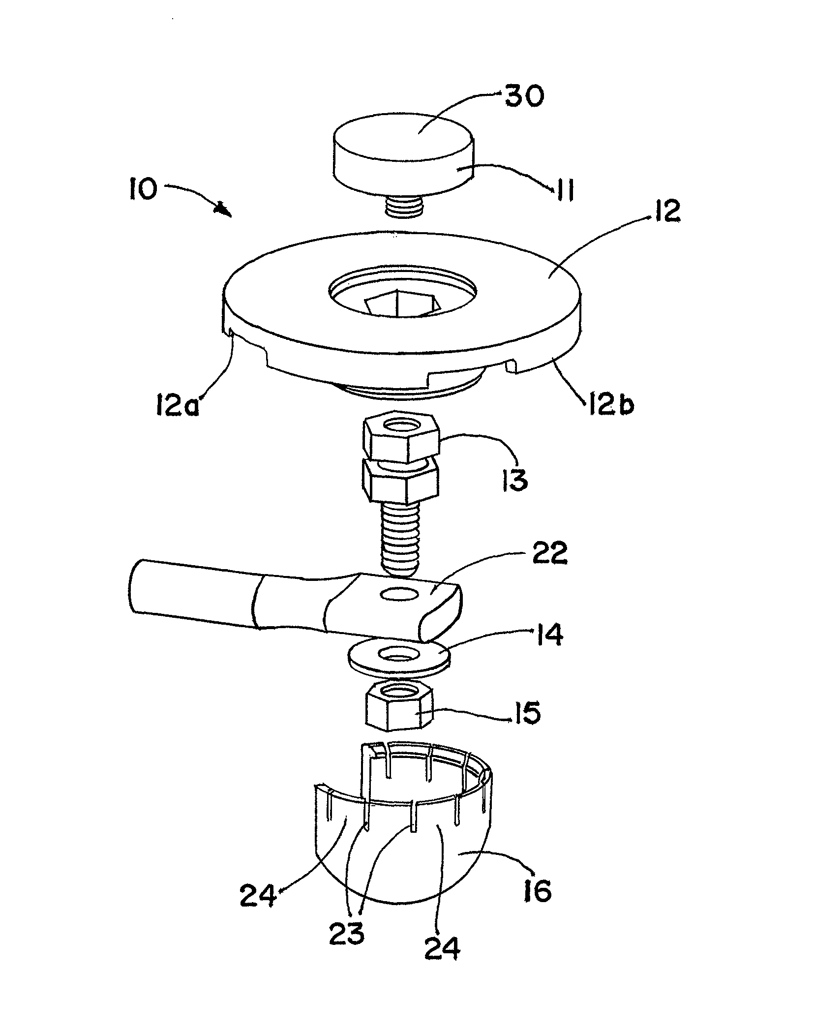
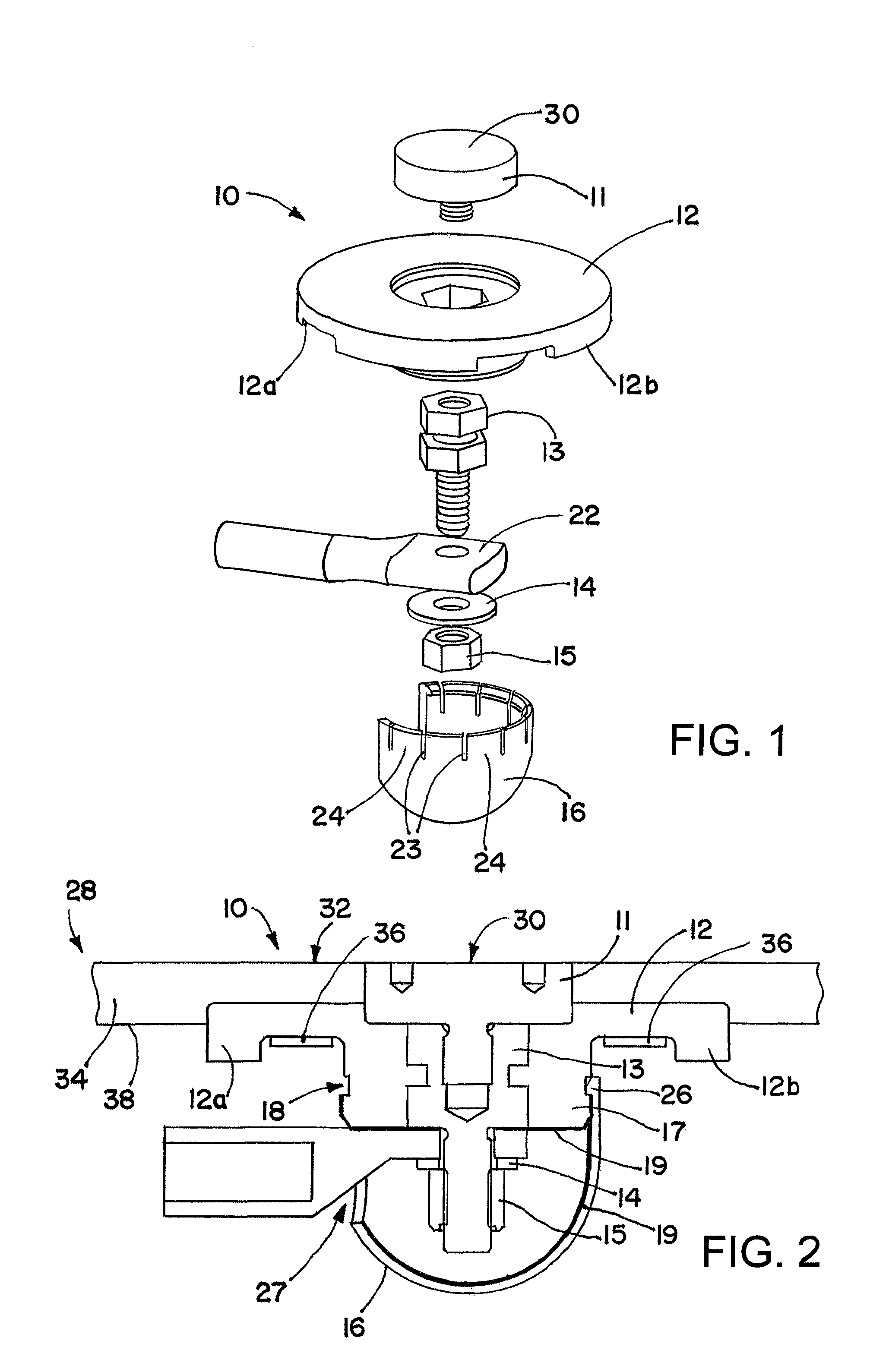
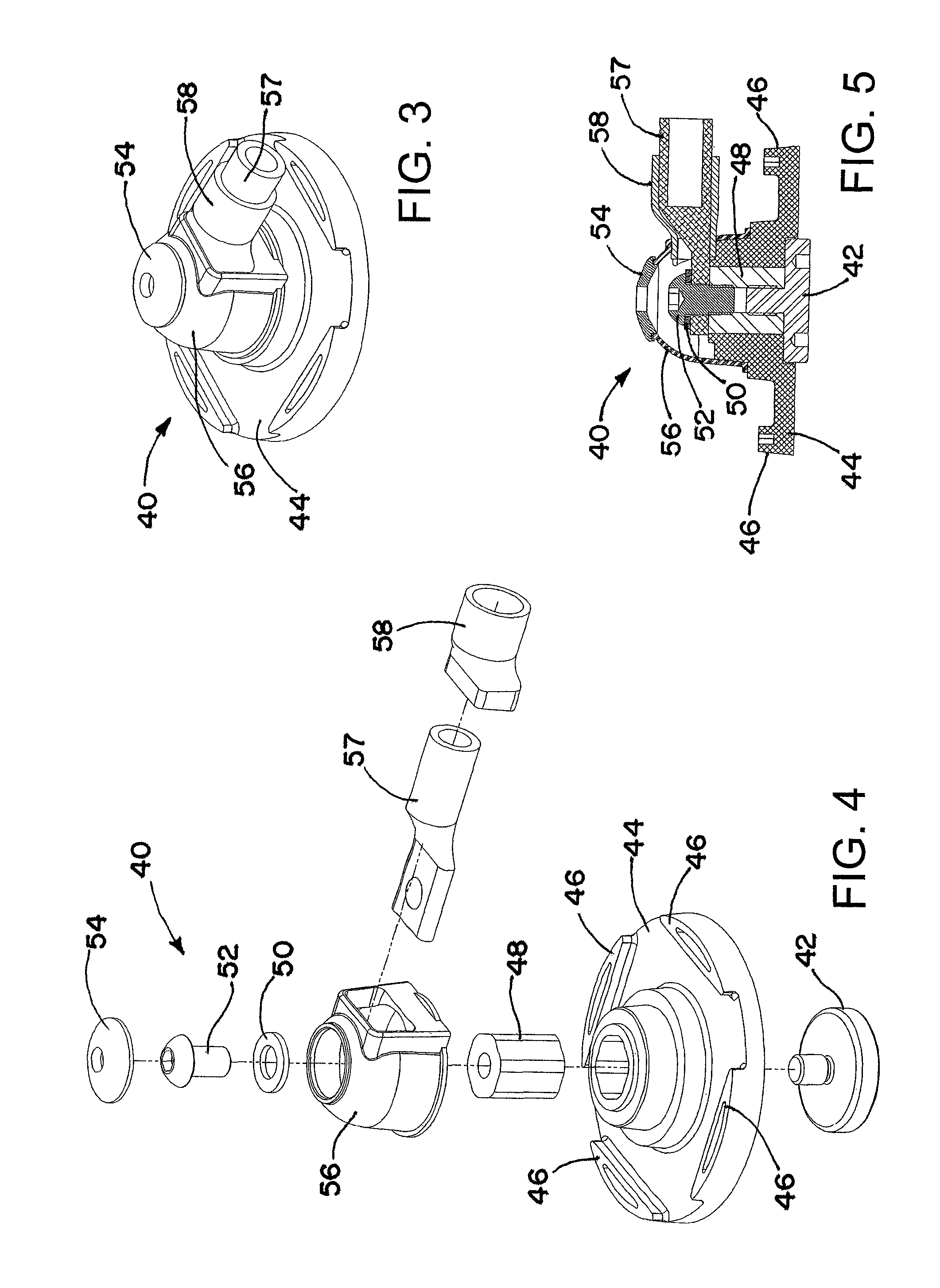
[0049]A receptor assembly for lightning protection of an object, such as a wind turbine blade, includes a receptor disk configured to be placed on a surface of the object, a receptor block insulator with an integral receptor block, a cover that engages the receptor block insulator, and a cap that engages the cover. The receptor disk and the receptor block may be made of electrically conductive materials, and the cover and the cap and the receptor block insulator may define a chamber among them that is lined with an electrically-conductive coating sandwiched between relatively high dielectric media to electrically isolate and shield internal parts of the receptor assembly from receiving a lightning strike directly.

[0050]The receptor system that is subsequently described is configured to minimize electrical field stress of the internally conductive connection components by addressing the relative geometries of conductive objects and altering the field apparent shape of these objects. ...


PUM

PropertyMeasurementUnit
perimeteraaaaaaaaaa
thicknessaaaaaaaaaa
electrically conductiveaaaaaaaaaa

Abstract

A receptor assembly for lightning protection of an object, such as a wind turbine blade, includes a receptor disk configured to be placed on a surface of the object, a receptor block insulator with an integral receptor block, a cover that engages the receptor block insulator, and a cap that engages the cover. The receptor disk and the receptor block may be made of electrically conductive materials, and the cover, and the cap, and the receptor block insulator may define a chamber among them that is lined with an electrically-conductive coating sandwiched between relatively high dielectric media to electrically isolate and shield internal parts of the receptor assembly from receiving a lightning strike directly.

Description

[0001]This application claims priority under 35 USC 119 to U.S. Provisional Application No. 61 / 366,996, filed Jul. 23, 2010.BACKGROUND OF THE INVENTION[0002]1. Field of the Invention[0003]This invention is in the field of lightning protection for wind turbine blades and other objects.[0004]2. Description of the Related Art[0005]At present there are three primary methods proposed in the industry for protecting wind turbine blades from lightning strikes: tip receptors, surface receptors, and blade coverings.[0006]Tip receptors are typically a cylindrical conductor that protrudes through the distal fin of the blade or a conductive end cap on the distal fin, which matches the blade profile. Some of these receptors are equipped with condensation drains. They are always connected to an earthing conductor, or earthing electrode, running laterally through the cavity of the turbine blade terminating at the blade root. Some configurations use an anchoring block, known as a receptor block, loc...

Claims


Application Information

Patent Timeline
Patent Type & Authority Patents(United States)
IPC IPC(8): F03D9/00F01D5/14
CPCF03D11/0033Y02E10/722H02G13/00H02G13/40F03D80/30Y10T29/4932Y02E10/72
Inventor FLEMMING, MATTHEWCAIE, MATTHEWKAY, ETHANAMBROGIO, NICHOLAS J.
Owner ERICO INT
Why Eureka
Try Eureka