
Piezoelectric vibrator element and method of manufacturing the same

Inactive Publication Date: 2012-02-02
SEIKO EPSON CORP
View PDF2 Cites 1 Cited by
  • Summary
  • Abstract
  • Description
  • Claims
  • Application Information

AI Technical Summary

Benefits of technology

[0007]An advantage of some aspects of the invention is to provide an inverted-mesa piezoelectric vibrator element having a slit, which is small in size and has little residual dross, and a method of manufacturing the piezoelectric vibrator element.
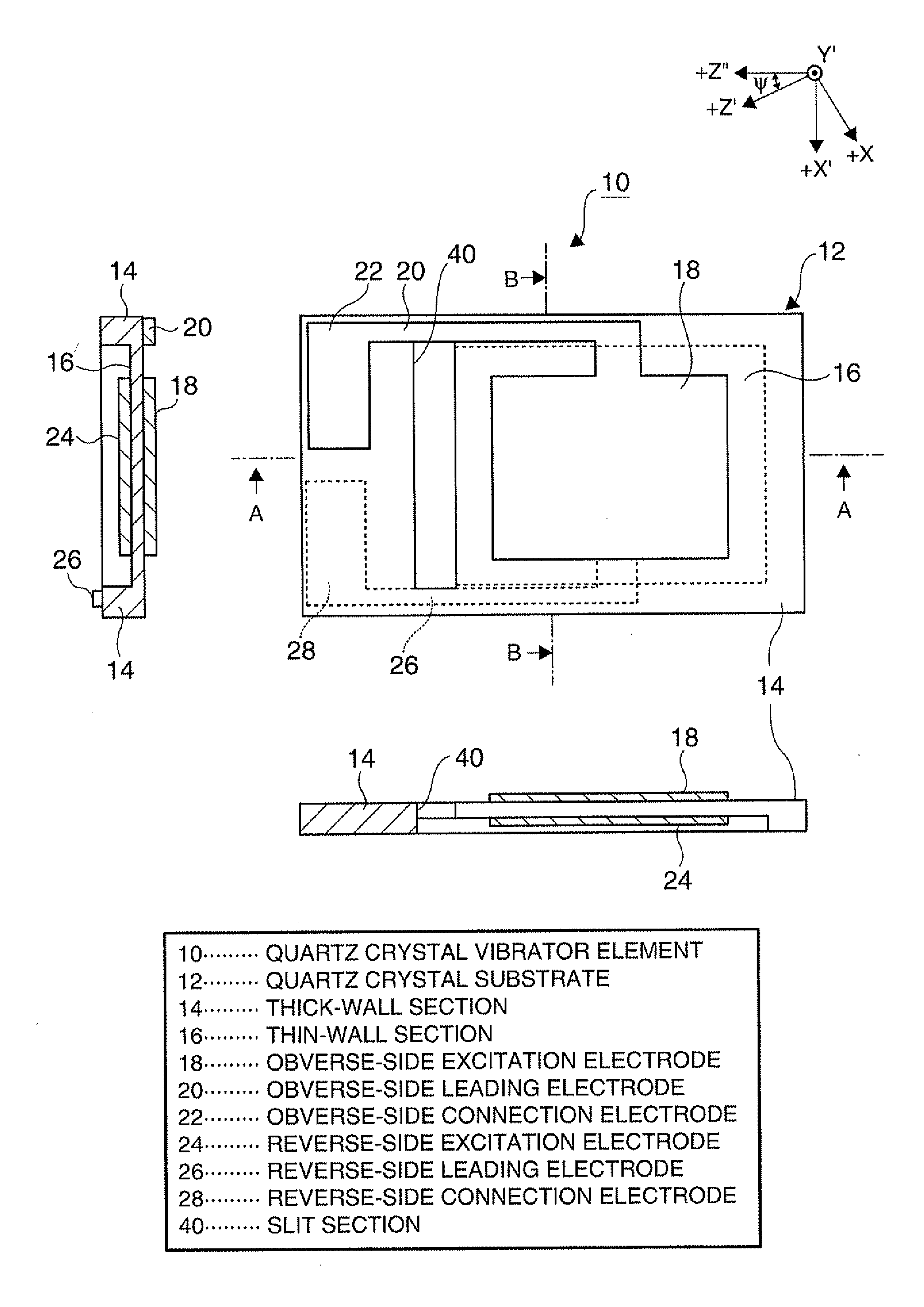
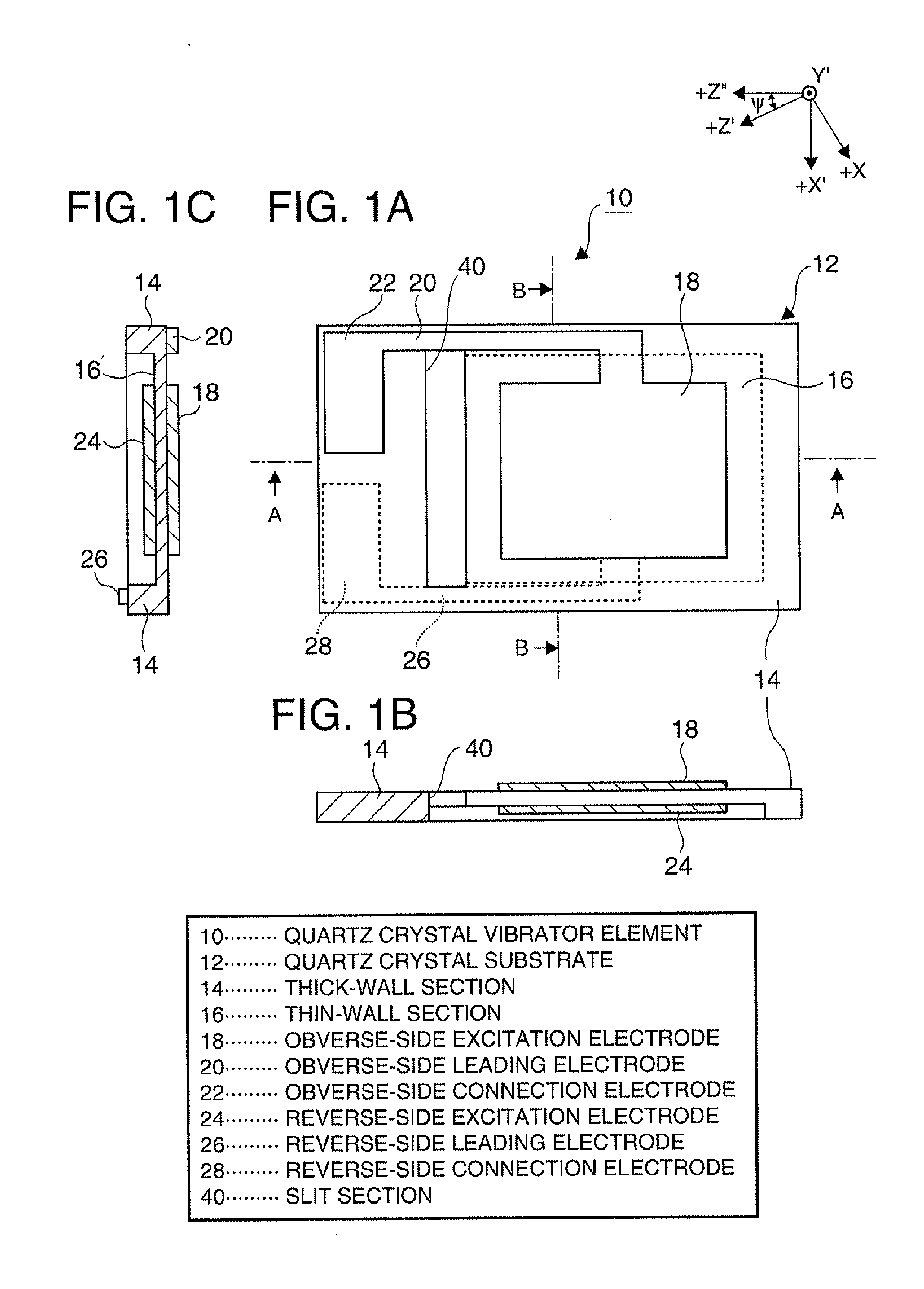
[0015]According to this application example of the invention, since the connection electrode is disposed in the thick-wall section adjacent to the both end sides of the thin-wall section of the piezoelectric vibrator element, the both sides of the piezoelectric vibrator element can be fixed to the package, and thus, the impact resistance of the piezoelectric vibrator element can be improved. Further, the slit section is disposed in the area intervening between each of the thick-wall sections provided with the connection electrodes and the thin-wall section, it is possible to prevent the stress from the thick-wall section provided with the connection electrode to be connected to the package from propagating to the thin-wall section provided with the excitation electrode.Application Example 4
[0033]By adopting the configuration described above, it is possible to prevent the protrusion due to the etching anisotropy from appearing in the slit section.

Problems solved by technology

If the piezoelectric vibrator element is thus supported by the electrically conductive adhesive, there arises a problem that the distortion due to the difference in linear expansion coefficient between the piezoelectric vibrator element, the package, and the electrically conductive adhesive remains in the fixing section in the reflow process for curing the electrically conductive adhesive, and the stress from the fixing section to the vibrating section exerts a harmful influence on the vibration.
However, when forming the piezoelectric vibrator element from a quartz crystal, the manufacture of the quartz crystal using the wet etching is affected by the crystal orientation of the quartz crystal.
The residual dross problematically affects the vibration characteristics.
The area for the residual dross to be removed forms a large wasteful area.
Therefore, there arises a problem that it is not achievable to miniaturize the quartz crystal vibrator element, and it is not achievable to assure the sufficient number of quartz crystal vibrator elements obtained from one wafer.

Method used


Image

  • Piezoelectric vibrator element and method of manufacturing the same
  • Piezoelectric vibrator element and method of manufacturing the same
  • Piezoelectric vibrator element and method of manufacturing the same

Examples


Embodiment Construction

[0050]An embodiment of the invention will hereinafter be described in detail with reference to the accompanying drawings. FIG. 1A is a plan view of a quartz crystal vibrator element 10 viewed from the above, FIG. 1B is a cross-sectional view of the quartz crystal vibrator element 10 shown in FIG. 1A along the line A-A, and FIG. 1C is a cross-sectional view of the quartz crystal vibrator element 10 shown in FIG. 1A along the line B-B.

[0051]The quartz crystal vibrator element 10 is composed of a quartz crystal substrate 12, and electrode patterns 18, 20, 22, 24, 26, and 28 formed on the surface of the quartz crystal substrate 12.

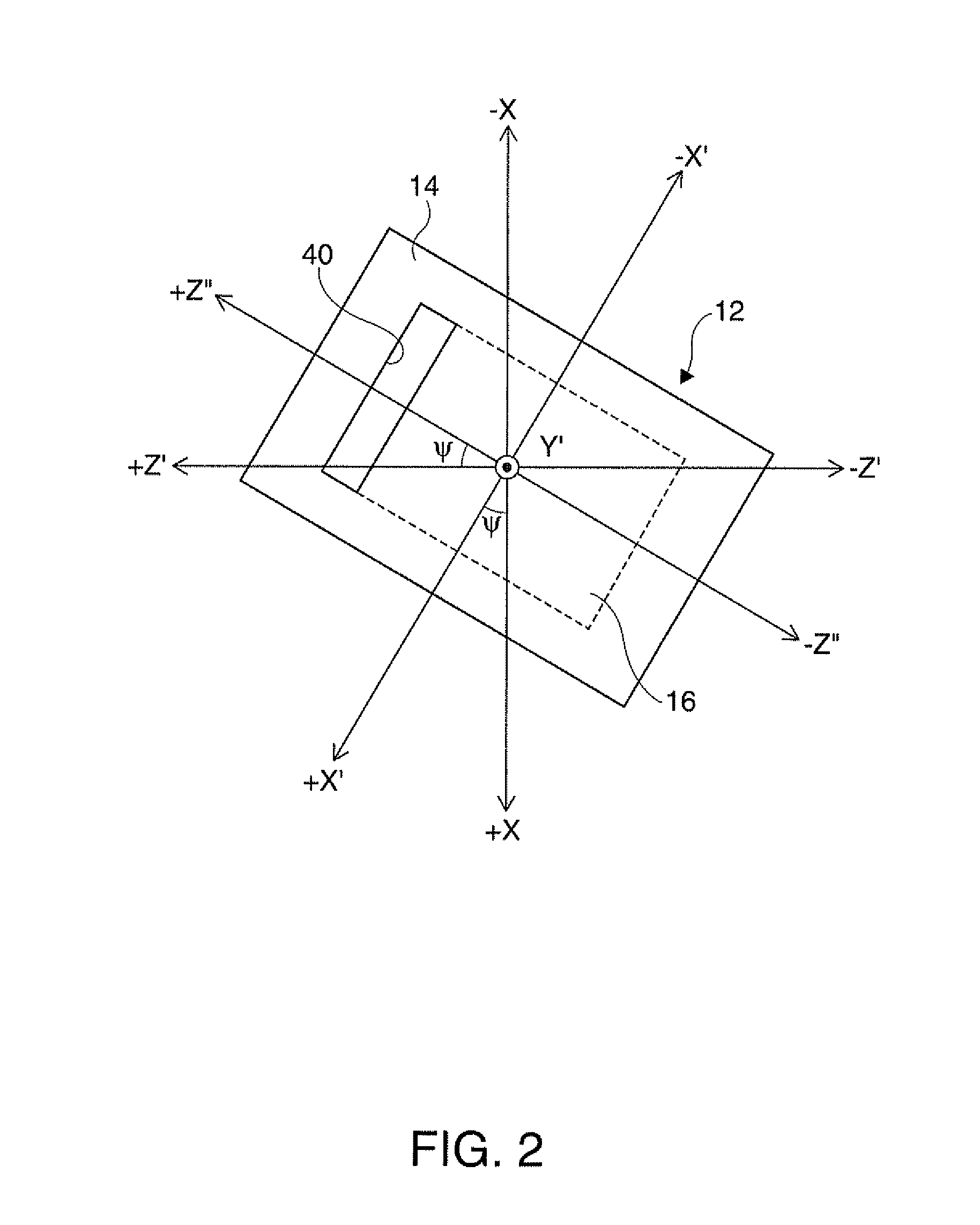
[0052]As the quartz crystal substrate 12 according to the present embodiment, the substrate obtained by performing so-called in-plane rotation on an AT-cut quartz crystal substrate is used. In a more detailed explanation, the AT-cut quartz crystal substrate denotes the quartz crystal substrate carved out so as to include a principal surface (a principal surfac...


PUM

PropertyMeasurementUnit
Angleaaaaaaaaaa
Angleaaaaaaaaaa
Angleaaaaaaaaaa

Abstract

A piezoelectric vibrator element provided by performing wet etching on a piezoelectric substrate includes: a thin-wall section including a vibrating section; a thick-wall section thicker than the thin-wall section; and a slit section penetrating in a thickness direction, wherein the slit section is disposed in an area intervening between the thin-wall section and the thick-wall section.

Description

BACKGROUND[0001]1. Technical Field[0002]The present invention relates to a piezoelectric vibrator element and a manufacturing method thereof, and in particular to an inverted-mesa piezoelectric vibrator element provided with a slit section and a manufacturing method thereof.[0003]2. Related Art[0004]In the past, as a mounting form of the piezoelectric vibrator element, there can be cited a form of applying an electrically conductive adhesive to thereby fixing the piezoelectric vibrator element to a package. If the piezoelectric vibrator element is thus supported by the electrically conductive adhesive, there arises a problem that the distortion due to the difference in linear expansion coefficient between the piezoelectric vibrator element, the package, and the electrically conductive adhesive remains in the fixing section in the reflow process for curing the electrically conductive adhesive, and the stress from the fixing section to the vibrating section exerts a harmful influence ...

Claims


Application Information

Patent Timeline
IPC IPC(8): H01L41/04H01L41/22H01L41/09H01L41/18H01L41/187H01L41/29H01L41/313H01L41/332H03H3/02H03H9/19
CPCH03H3/04Y10T29/42H03H9/19H03H9/02023
Inventor YASUIKE, RYOICHI
Owner SEIKO EPSON CORP
Learn More