Device for measuring the focal distance of a thermal lens

a thermal lens and focal distance technology, applied in measurement devices, material analysis through optical means, instruments, etc., can solve the problems of large volume, local decrease of refractive index, and difficult experimental implementation, and achieve the effect of small volum

Active Publication Date: 2012-02-02
COMMISSARIAT A LENERGIE ATOMIQUE ET AUX ENERGIES ALTERNATIVES
View PDF1 Cites 11 Cited by
  • Summary
  • Abstract
  • Description
  • Claims
  • Application Information

AI Technical Summary

Benefits of technology

[0054]The method may further include a step of focusing the exciting optical beam before it passes through the analyte by focusing means, which enables an analyte with a small size to be used.

Problems solved by technology

If the energy absorbed by the analyte is significant, the sudden increase in temperature by molecular relaxation results in an expansion of the medium and thus a local decrease in the refractive index.
However, it is worthy of note that the experimental implementation is quite delicate.
The concentration measurements pose the problem of the stability in the lighting intensity of the source and its possible absorption by the medium investigated.
The measurements performed can not be reliable because of the instability causing fluctuations in the intensity of laser sources, the instability in the transmission of the probe optical beam when the analyte absorbs the probe optical beam, and the mechanical instability inherent to the extremely accurate optical adjustments of the optical sources for the intersection between the exciting optical beam and the probe optical beam to be located at their optical axes.
Controlling this intersection at the micron scale is difficult because it depends on thermal variations, mechanical impacts and slight variations in the analyte refractive index, caused by a slight variation in temperature, or in the chemical composition of the analyte called “matrix effect” in the analysis field.
These disturbances condemn these measurement techniques because they have low reproductibility levels, only 30% according to some authors.
These techniques are often incompatible with the constraints of the physico-chemical analysis.
Another drawback of the devices which have moving parts such as those illustrated in FIGS. 2A, 2C and 2D is that they are often not robust enough.
Calibrating the device is complicated because of the local observation of the spatial interference and of a strongly altered wave front upon passing through the thermal lens.
Finally, the Shack-Hartmann analyser is a device with a low sensitivity and difficult to transpose to the quantitative measurement of chemical species.

Method used


Image

  • Device for measuring the focal distance of a thermal lens
  • Device for measuring the focal distance of a thermal lens
  • Device for measuring the focal distance of a thermal lens

Examples


Embodiment Construction

[0043]One object of the present invention is actually to provide a method for measuring the focal distance of a thermal lens created in an analyte which does not have the above-mentioned drawbacks and in particular, which is not sensitive to energy variations of the source generating the probe optical beam.

[0044]Another object of the invention is to provide such a method which does not depend on energy variations transmitted by the source generating the probe optical beam under the influence of its absorption by the analyte.

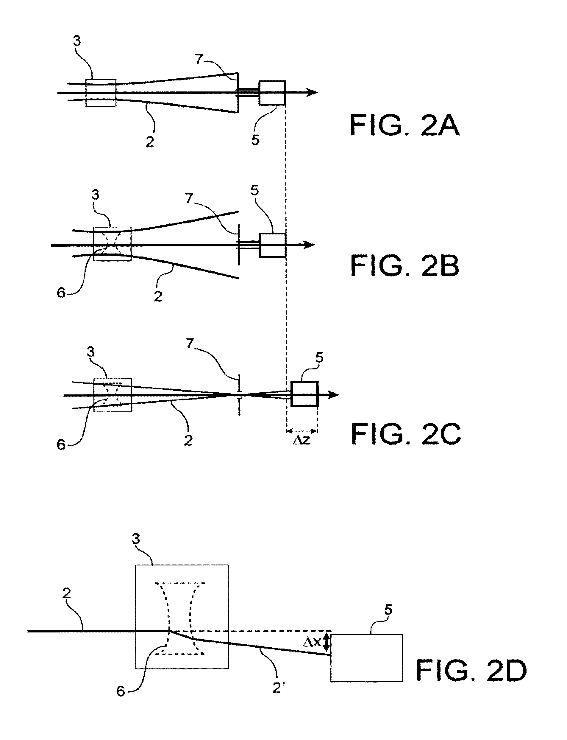
[0045]Still another object of the invention is to provide such a method which does not depend on slight geometrical variations at the intersection between the probe optical beam and the exciting optical beam.

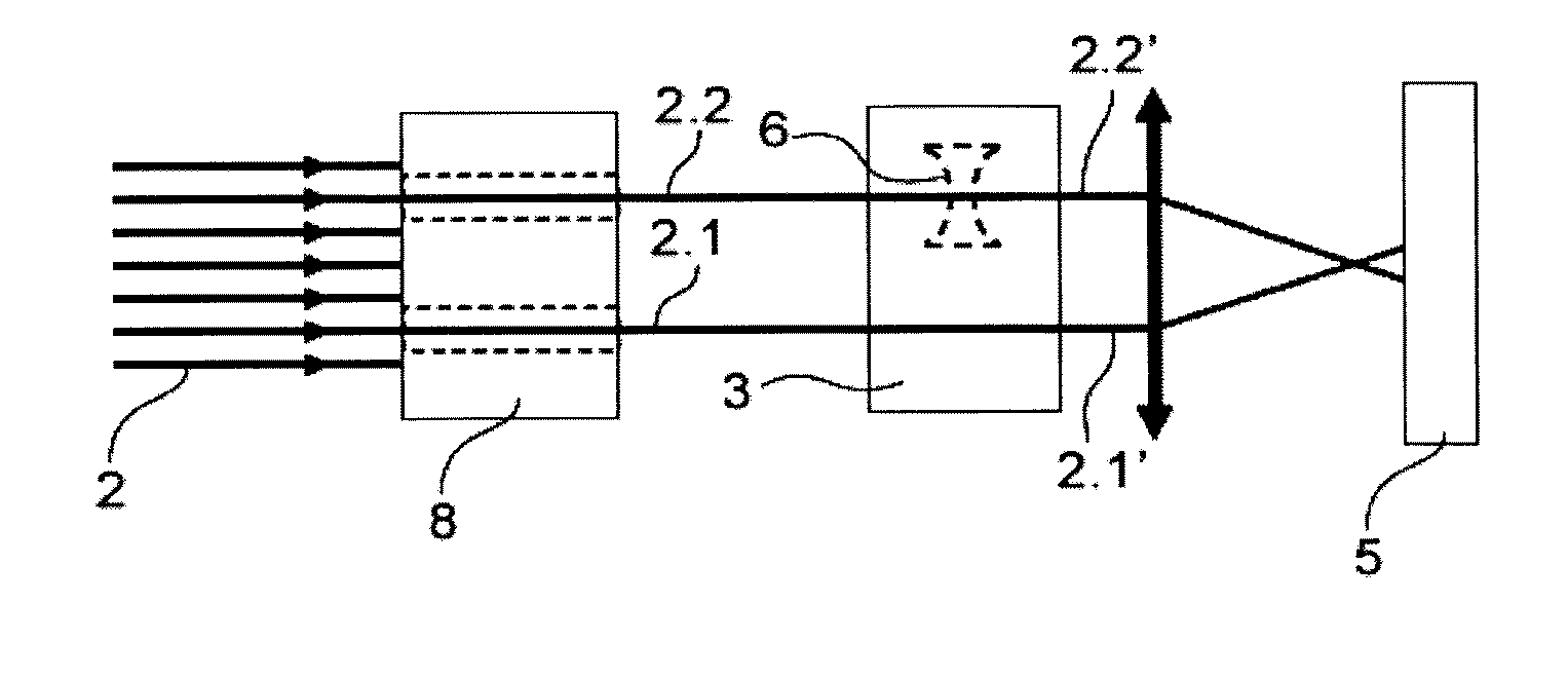
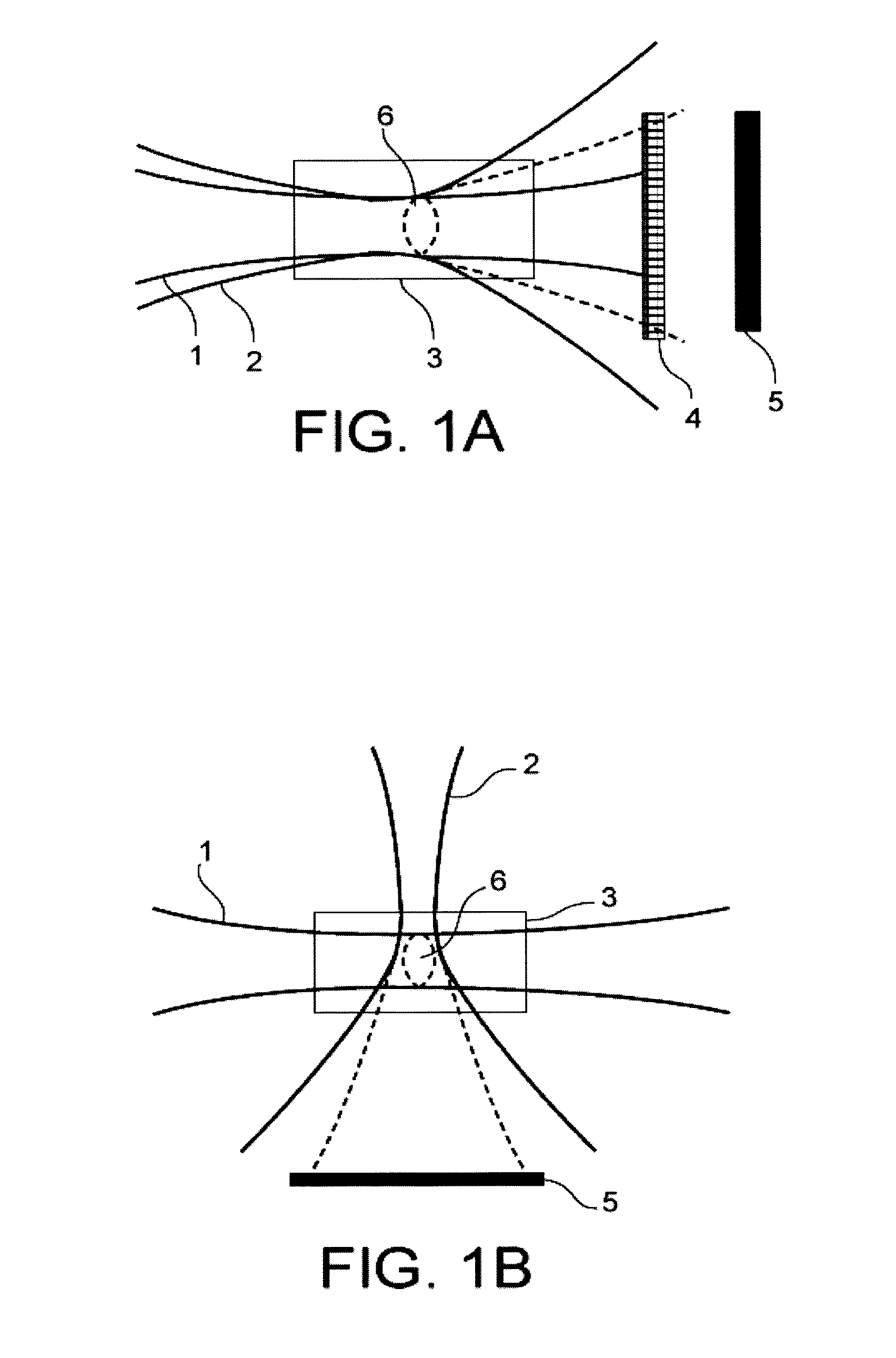
[0046]A method for measuring the focal distance of a thermal lens created in an analyte according to the invention includes the steps of:

[0047]providing an exciting optical beam by an exciting optical source, such exciting optical beam passing through the ana...


PUM


Abstract

A method for measuring focal distance of a thermal lens located in an analyte, the method including: providing an exciting optical beam passing through the analyte and creating the thermal lens therein; emitting a coherent probe optical beam passing through the analyte and being propagated substantially perpendicular to the exciting optical beam; intercepting the probe optical beam by a detector after passing through the analyte; focusing the probe optical beam upstream or downstream of the thermal lens such that only a fraction of the probe optical beam passes through the thermal lens; acquiring an interference image by the detector; and processing the interference image to calculate the focal distance of the thermal lens. Such a method may find application in physico-chemical analysis of the analyte.

Description

TECHNICAL FIELD[0001]The present invention relates to a device for measuring the focal distance of a thermal lens created in an analyte and a device for physico-chemically analysing the analyte.STATE OF THE PRIOR ART[0002]Devices for measuring the focal distance of a thermal lens formed in an analyte are already known. Such a device enables in particular the analyte to be physico-chemically analysed. The principle of the formation of a thermal lens will be first reminded.[0003]When an optical beam is absorbed by a molecule, this results in an increase in the internal energy thereof. The molecule switches to an unstable energy state, which causes it to remove the excess energy to restore its previous stable state. Several ways are then possible. It can emit an optical radiation, that is luminescence, it can emit a thermal radiation, that is vibration-rotation phenomenon, there can also be a phenomenon of energy transfer to other surrounding chemical systems.[0004]The energy loss by t...

Claims


Application Information

Patent Timeline
Patent Type & Authority Applications(United States)
IPC IPC(8): G01B9/00
CPCG01N21/171G01N2021/451G01N2021/1712G01N21/45
Inventor COUSTON, LAURENTCANTO, FABRICE
Owner COMMISSARIAT A LENERGIE ATOMIQUE ET AUX ENERGIES ALTERNATIVES
Why Eureka
Try Eureka