Optical information record/reproduction apparatus and reproduction apparatus
a technology of optical information record and reproduction apparatus, applied in the field of optical information record/reproduction apparatus and reproduction apparatus, to achieve the effect of large memory capacity
- Summary
- Abstract
- Description
- Claims
- Application Information
AI Technical Summary
Benefits of technology
Problems solved by technology
Method used
Image
Examples
first embodiment
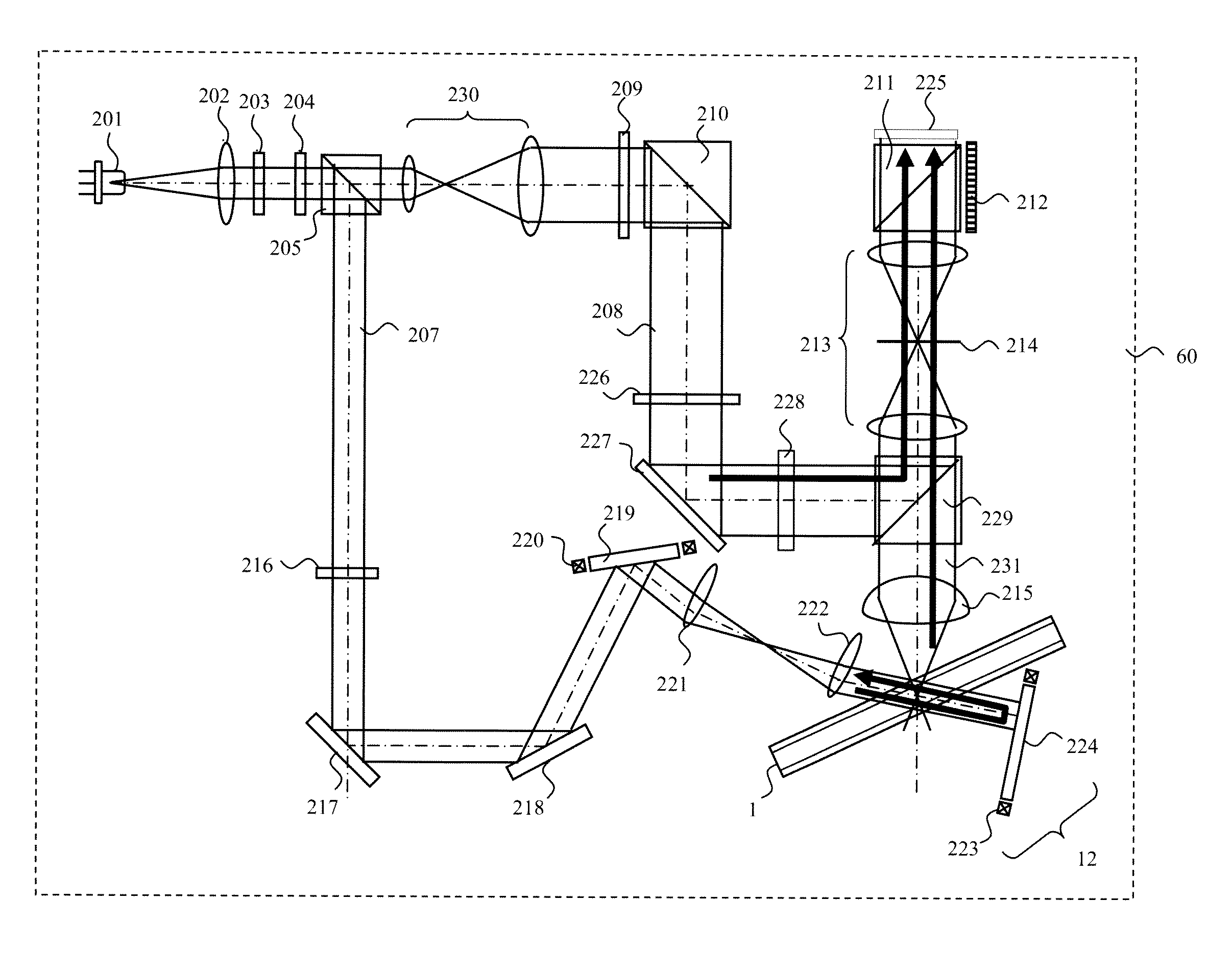
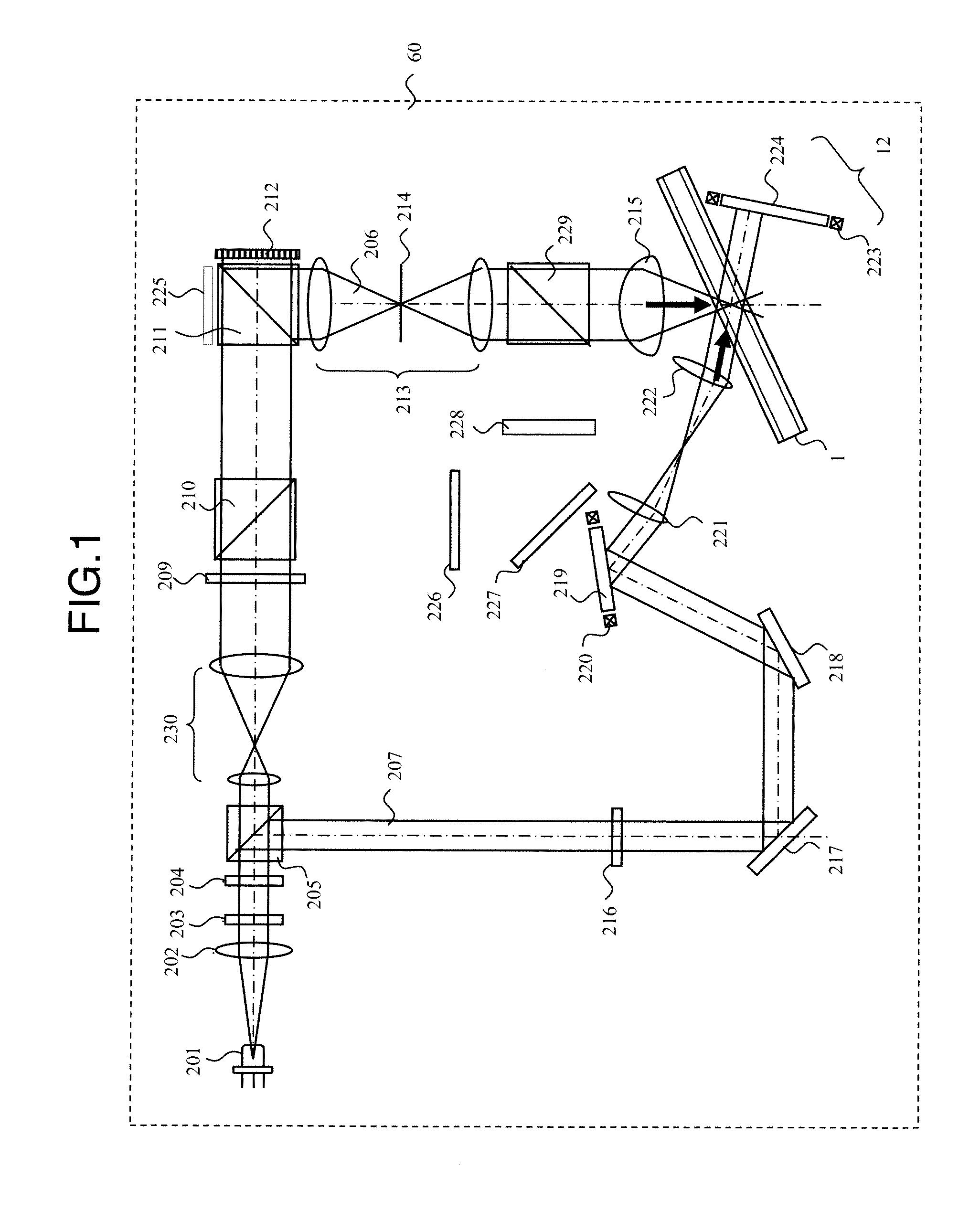
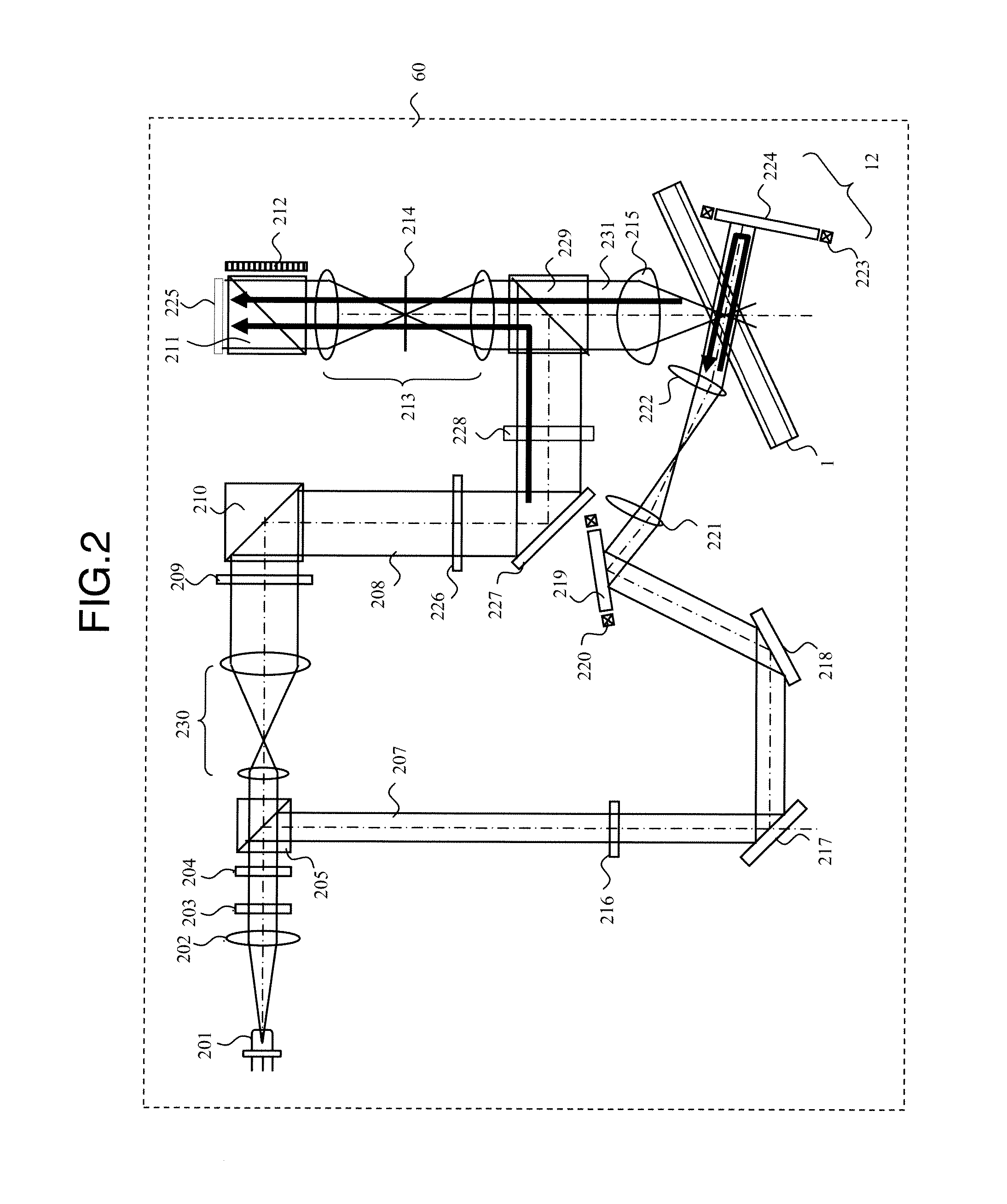
[0027]FIG. 1 is a general diagram showing a first embodiment of an optical pickup apparatus 60 of the present invention when information is recorded. The optical beam emitted from a light source 201 transmits through a collimate lens 202 and enters a shutter 203. When the shutter 203 is open, the optical beam passes through the shutter 203, has its polarization direction controlled by a polarization direction conversion element 204, configured by a half wave plate, so that the ratio between P-polarized light and S-polarized light becomes a desired ratio and, after that, enters a polarizing beam splitter 205.
[0028]The optical beam that has passed through the polarizing beam splitter 205 has its optical beam diameter expanded by a beam expander 230 and, via a polarization direction conversion element 209, a polarizing beam splitter 210, and a polarizing beam splitter 211, enters a spatial light modulator 212. The optical beam is changed by the spatial light modulator 212 to page data ...
second embodiment
[0042]FIG. 4 is a general diagram showing a second embodiment of an optical pickup apparatus 60 of the present invention, which aims to streamline the optical system of the first embodiment. FIG. 4 shows the recording operation.
[0043]The optical beam emitted from a light source 201 transmits through a collimate lens 202 and enters a shutter 203. When the shutter 203 is open, the optical beam passes through the shutter 203, has its polarization direction controlled by a polarization direction conversion element 204, configured by a half wave plate, so that the light quantity ratio between P-polarized light and S-polarized light becomes a desired ratio and, after that, enters a polarizing beam splitter 205.
[0044]The optical beam that has passed through the polarizing beam splitter 205 has its optical beam diameter expanded by a beam expander 230 and, via a polarization direction conversion element 209 and a polarizing beam splitter 211, enters a spatial light modulator 212. A signal b...
third embodiment
[0054]FIG. 8 is a diagram showing a whole configuration of a holographic memory apparatus that records and / or reproduces digital information using holography. The holographic memory apparatus comprises an optical pickup apparatus 60 with the configuration such as that shown in FIG. 1 and FIG. 4, a disc cure optical system 80, a disc rotation angle detection optical system 90, and a rotation motor 70 and has the configuration in which an optical information recording medium 1 may be rotated by the rotation motor 70.
[0055]The optical pickup apparatus 60 emits the reference beam and the signal beam onto the optical information recording medium 1 to record digital information via holography.
[0056]At this time, the information signal to be recorded is transmitted to a spatial light modulator 212 in the optical pickup apparatus 60 by a controller 89 via a signal generation circuit 86, and the signal beam is modulated by the spatial light modulator.
[0057]To reproduce the information record...
PUM
 Abstract
Description
Claims
Application Information
 - R&D
- Intellectual Property
- Life Sciences
- Materials
- Tech Scout
- Unparalleled Data Quality
- Higher Quality Content
- 60% Fewer Hallucinations
Browse by: Latest US Patents, China's latest patents, Technical Efficacy Thesaurus, Application Domain, Technology Topic, Popular Technical Reports.
© 2025 PatSnap. All rights reserved.Legal|Privacy policy|Modern Slavery Act Transparency Statement|Sitemap|About US| Contact US: help@patsnap.com


