Beam Quality of the Monoblock Laser Through Use of a 1.5 Micron External Cavity Partial Reflector

a monoblock laser and partial reflector technology, applied in the direction of laser details, active medium materials, active medium shape and construction, etc., can solve the problems of large heavy and expensive, bulky known laser range finders, etc., to reduce the beam divergence of known monoblock lasers and improve brightness

Inactive Publication Date: 2012-02-02
UNITED STATES OF AMERICA THE AS REPRESENTED BY THE SEC OF THE ARMY
View PDF2 Cites 6 Cited by
  • Summary
  • Abstract
  • Description
  • Claims
  • Application Information

AI Technical Summary

Benefits of technology

[0006]A monoblock laser cavity having optical components is disclosed for a short-pulse laser. One exemplary embodiment of a monoblock laser cavity includes a gain medium having one coated end surface, a juncture in the medium, and another end surface; a passive Q-switch having one end surface optically facing said another end surface of the gain medium; and an optical parametric oscillator crystal having one end surface and an output face. The one end surface of the optical parametric oscillator crystal optically is configured to face another end surface of the Q-switch. An output coupler is placed on the output face of the optical parametric oscillator crystal. Such a monoblock laser can improve the brightness and decrease the beam divergence of the monoblock laser.

Problems solved by technology

Unfortunately, known laser range finders are bulky, heavy and expensive.
Unfortunately, the beam divergence of known monoblock lasers is rather large (typically between 8 and 14 mRad).

Method used


Image

  • Beam Quality of the Monoblock Laser Through Use of a 1.5 Micron External Cavity Partial Reflector
  • Beam Quality of the Monoblock Laser Through Use of a 1.5 Micron External Cavity Partial Reflector
  • Beam Quality of the Monoblock Laser Through Use of a 1.5 Micron External Cavity Partial Reflector

Examples


Embodiment Construction

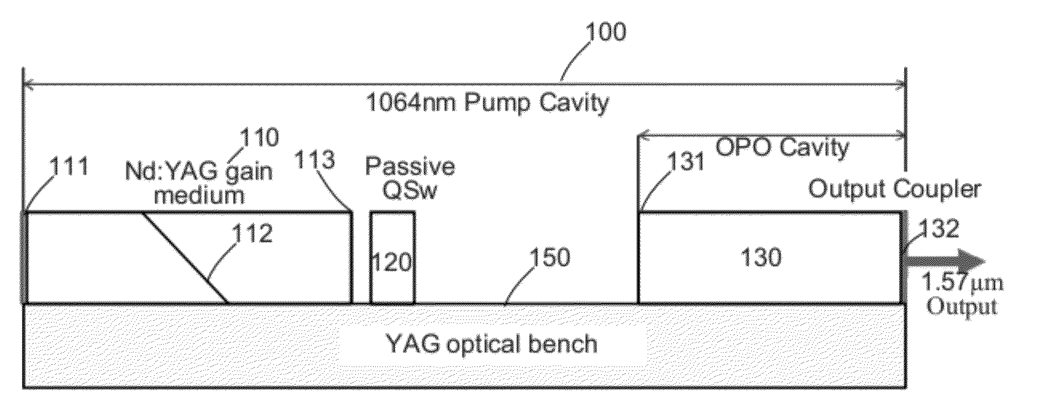
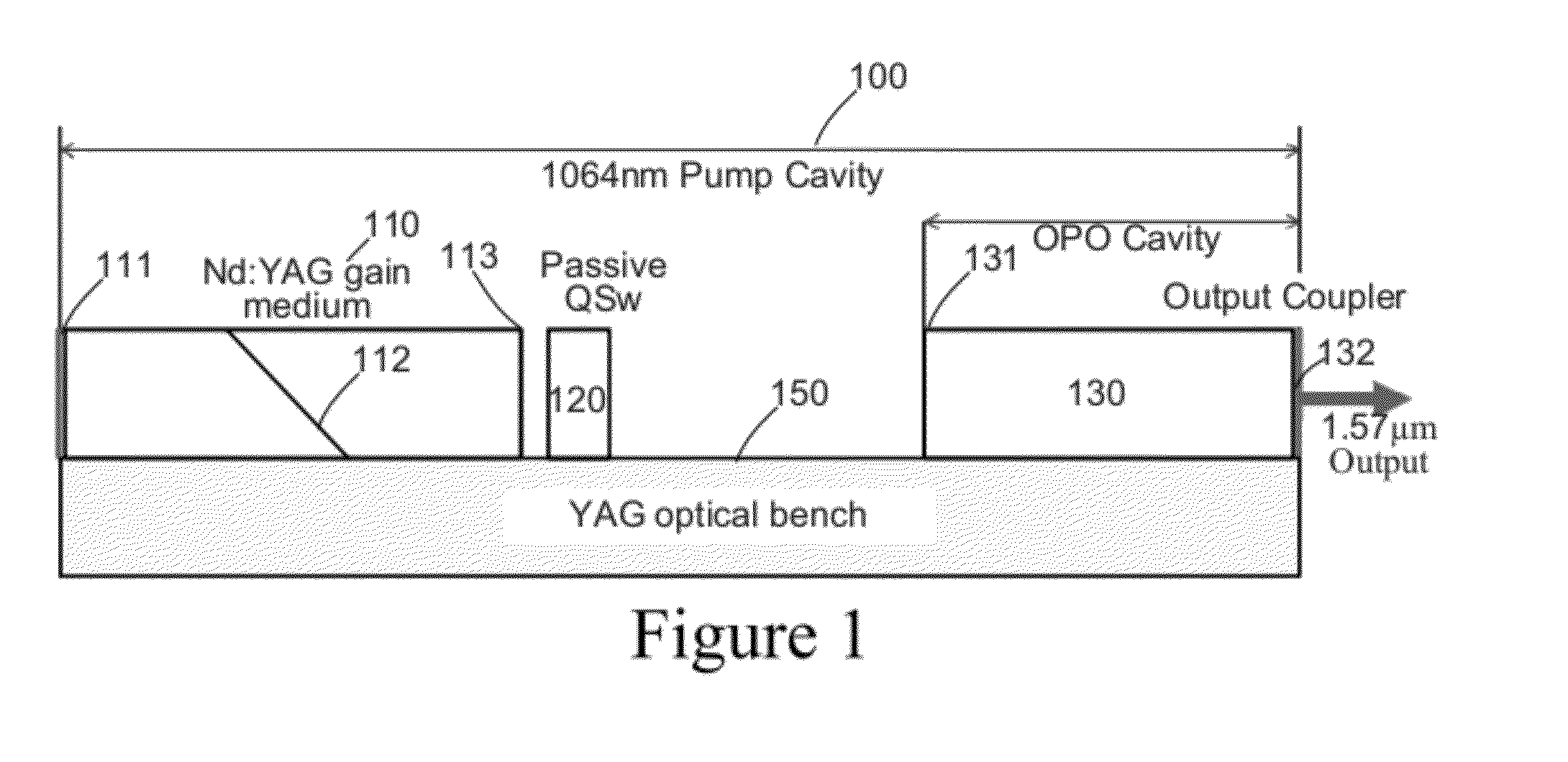
[0013]FIG. 1 depicts an exemplary monoblock laser cavity. It is shown as a flat-flat or stable resonator configuration. As configured in relation to a YAG optical bench 150, an Nd:YAG gain medium 110 has one end surface 111 coated to have a surface optical property, e.g., High-Reflection Coating of HR@1064 nm; and a juncture 112 in the medium 110 having a Brewster's angle for polarization. A passive Q-switch 120 (e.g., Cr4+:YAG passive QSw) has one end surface optically facing another end surface 113 of the Nd:YAG gain medium 110. An optical parametric oscillator (OPO) crystal 130 is configured in relation to another end of the YAG optical bench 150, one end surface 131 of the OPO crystal 130 being optically facing another end surface of the Q-switch 120. The one end surface 131 of the OPO crystal 130 can have surface coatings, e.g., Anti-Reflection Coating of AR@1064 nm, and High-Reflection Coating of HR@1570 nm. Such an exemplary configuration can be acutely sensitive to angular d...


PUM


Abstract

A monoblock laser cavity incorporates optical components for a short-pulse laser. These optical components are ‘locked’ into alignment forming an optical laser cavity for flash lamp or diode laser pumping. The optical laser cavity does not need optical alignment after it is fabricated, increasing the brightness of the monoblock laser.

Description

GOVERNMENT INTEREST[0001]The invention described herein may be manufactured, used, sold, imported, and / or licensed by or for the Government of the United States of America.FIELD OF THE DISCLOSURE[0002]The disclosure relates to a monoblock laser cavity having optical components for a short-pulse laser.BACKGROUND INFORMATION[0003]Laser range finders are an increasingly vital component in high precision targeting engagements. The precise and accurate range to target information is an essential variable for fire control of weapons. This information is easily, and timely, provided by laser range finders.[0004]Unfortunately, known laser range finders are bulky, heavy and expensive. These laser range finders were not developed with the individual field use in mind.[0005]Monoblock laser makes the development / fabrication of a very low cost, compact laser range finder feasible. Unfortunately, the beam divergence of known monoblock lasers is rather large (typically between 8 and 14 mRad). Such...

Claims


Application Information

Patent Timeline
Patent Type & Authority Applications(United States)
IPC IPC(8): H01S3/11
CPCH01S3/025H01S3/0606H01S3/0621H01S3/07H01S3/0625H01S3/082H01S3/1083H01S3/113H01S3/08054
Inventor NETTLETON, JOHN E.GOLDBERG, LEWBARR, DALLAS N.
Owner UNITED STATES OF AMERICA THE AS REPRESENTED BY THE SEC OF THE ARMY
Why Eureka
Try Eureka