Industrial x-ray generator

a generator and x-ray technology, applied in the field of industrial x-ray generators, can solve the problems of bulkiness and heavy weight of x-ray generators using high-pressure gas containers, not providing compact and lightweight insulation structures, and reducing the efficiency of x-ray generators. the effect of hea

Active Publication Date: 2012-02-02
RIGAKU CORP
View PDF0 Cites 20 Cited by
  • Summary
  • Abstract
  • Description
  • Claims
  • Application Information

AI Technical Summary

Benefits of technology

[0034]The thermal conductivity of the molded member is desirably not less than 10 W / (m·K). Then, it is possible to prevent heat from being accumulated in the industrial X-ray generator and the X-ray generator from becoming unnecessarily hot.
[0035]In an industrial X-ray generator according to the present invention, the cathode desirably emit electrons on the basis of field emission. Then, the industrial X-ray generator can be downsized and made lightweight if compared with an arrangement of using a thermal electron emission type electron emitting element that employs a filament.

Problems solved by technology

Conventional industrial X-ray generators using high-pressure gas containers are accompanied by a problem of bulkiness and heavyweight because high-pressure containers have to be used.
Industrial X-ray generators having a cathode formed by using a filament require an arrangement for cooling the power source for filament and also the filament section to give rise to a problem of being large and heavy.
However, Jpn. Pat. Appln. Laid-Open Publication No. 6-267692 (Patent Document 3) only discloses an apparatus where only a cable receptacle and an X-ray tube are covered by a molded member and hence it does not provide a compact and lightweight insulated structure where both a high-voltage section and an X-ray tube are covered by a molded member.
Since an X-ray tube and a high-voltage generating section are arranged at mutually unrelated respective positions in each of these known apparatus, the entire apparatus including an X-ray tube and a high-voltage generating section inevitably becomes large.
Then, there arises a problem that the entire apparatus becomes very heavy due to the lead it contains.

Method used


Image

  • Industrial x-ray generator
  • Industrial x-ray generator
  • Industrial x-ray generator

Examples


first embodiment

of Industrial X-Ray Generator

[0050]Now, embodiments of industrial X-ray generator according to the present invention will be described below. It may not be necessary to say that the present invention is by no means limited to those embodiments. While the drawings are referred to in the following description, components of apparatus may be illustrated with dimensional proportions that are different from the real ones for the purpose of illustrating characteristic parts of the embodiments in an easily understandable fashion.

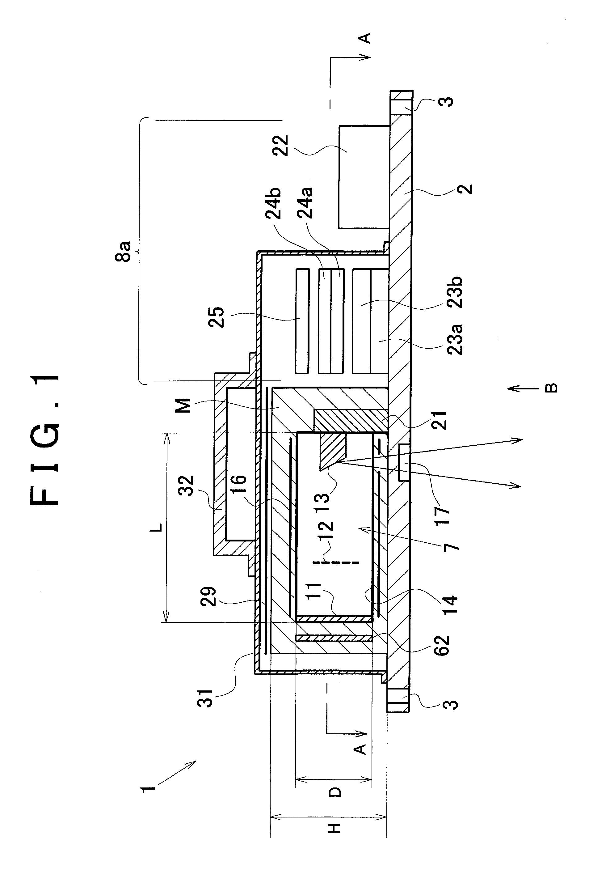
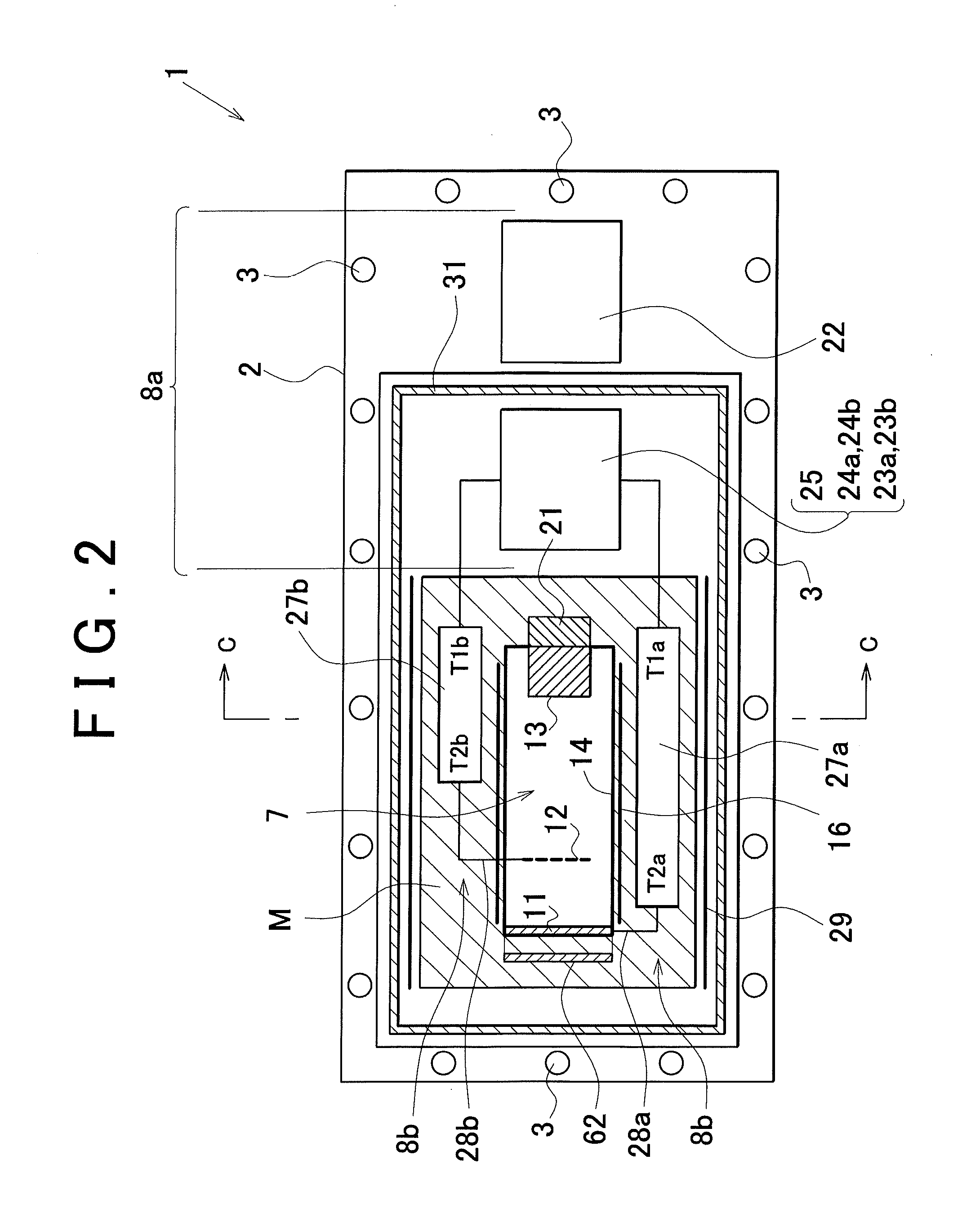
[0051]FIG. 1 is a schematic longitudinal cross-sectional front view of an embodiment of industrial X-ray generator according to the present invention. FIG. 2 is a schematic cross-sectional plan view taken along line A-A in FIG. 1. FIG. 3 is a schematic bottom view of the industrial x-ray generator as viewed in the direction of arrow B in FIG. 1. FIG. 4A is a schematic cross-sectional lateral view taken along line C-C in FIG. 2, showing the short-side direction of t...

modified embodiment

[0114]FIG. 10 illustrates an arrangement of the ceramic capacitors 51, the diodes 52 and the resistors R1 to R4 of the booster circuit 27a for the cathode and the booster circuit 27b for the grid that is different from the arrangement shown in FIG. 4A. With this modified arrangement, the ceramic capacitors 51 are obliquely arranged in the vertical direction so that this modified embodiment is slightly taller than the embodiment shown in FIG. 4A but the transversal dimensions thereof are greatly reduced from the embodiment of FIG. 4A.

second embodiment

of Industrial X-Ray Generator

[0115]FIG. 11 illustrates the high-voltage power supply section of another embodiment of industrial X-ray generator according to the present invention. Now, this embodiment will be described below.

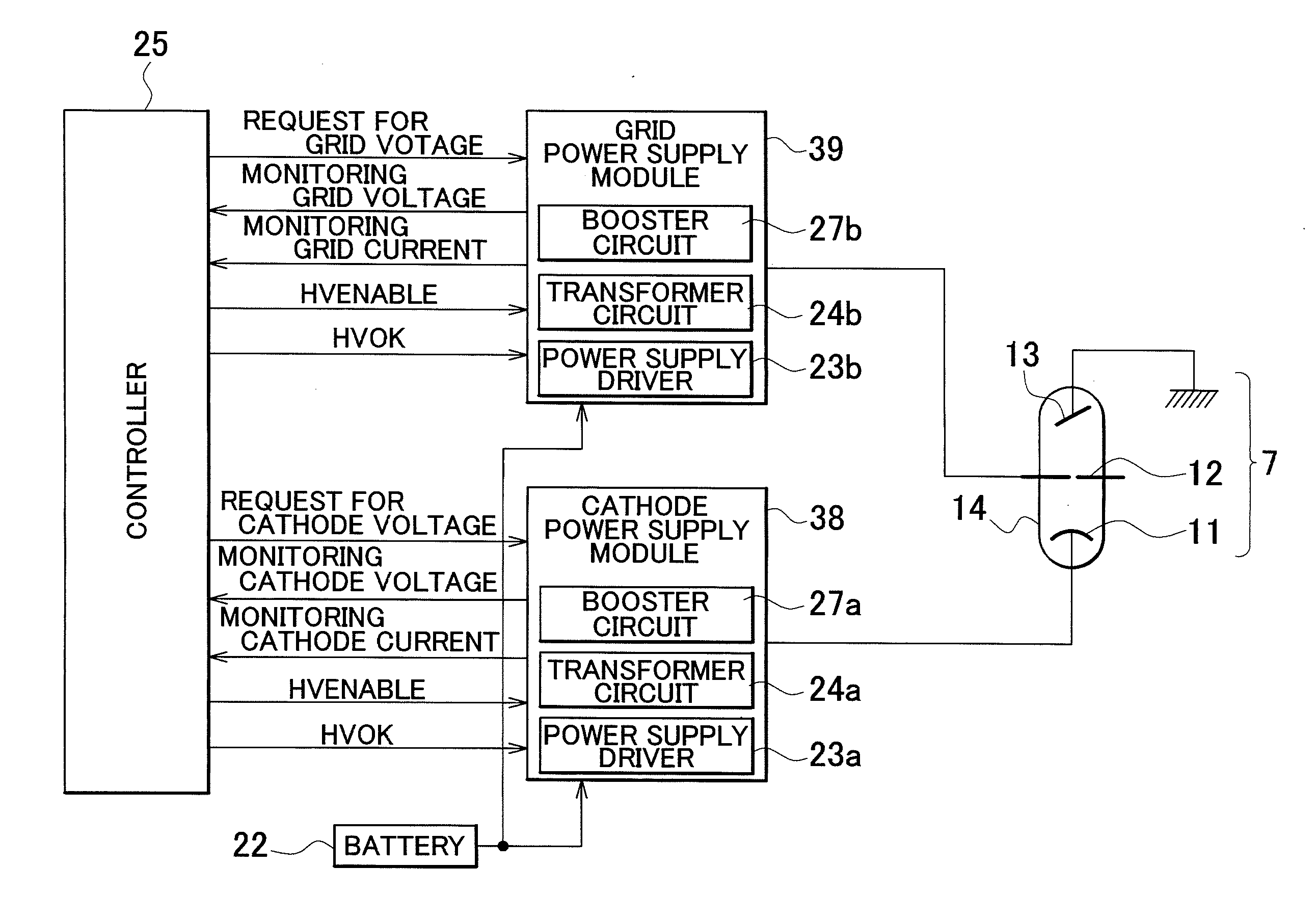
[0116]The resistors R1, R2, R3 and R4 for voltage monitoring are connected in series to the lead wire from the cathode 11 in the high-voltage power supply section of the embodiment shown in FIG. 8. The applied high voltage is lowered by these resistors and the lowered voltage is measured at the voltage monitoring terminal 46. The measurement data are transmitted to the controller 25 shown in FIG. 6 and used by the controller 25 as control data. In short, the voltage measurement circuit that includes the resistors R1, R2, R3 and R4 measures the voltage at the final stage of the Cockcroft-Walton circuit 43 in the embodiment shown in FIG. 8.

[0117]On the other hand, in the high-voltage power supply section of the embodiment shown in FIG. 11, a voltage measurement c...


PUM


Abstract

An X-ray generator includes a booster circuit formed by sequentially connecting a plurality of boosting steps extending from a low-voltage terminal to a high-voltage terminal of its own.
The booster circuit is arranged in a lateral region of the X-ray tube so as to make the low-voltage terminal of its own correspond to the anode of the X-ray tube and the high-voltage terminal of its own correspond to the cathode of the X-ray tube. A lead wire extending from the cathode to the outside of the X-ray tube is connected to the high-voltage terminal of the booster circuit. A molded member containing insulating resin is formed to shield at least a cathode side end part of the X-ray tube, the lead wire outwardly extending from the cathode side end part and a high-voltage terminal side end part of the booster circuit.

Description

BACKGROUND OF THE INVENTION[0001]1. Field of the Invention[0002]The present invention relates to an industrial X-ray generator designed to drive electrons emitted from a cathode to hit an anode and thereby generate X-rays from the anode so as to be used for non-destructive examinations of structures such as pipes of plant piping.[0003]2. Description of the Related Art[0004]X-ray generators having a cathode formed by using a tungsten filament as electron source are known. For example, Jpn. Pat. Appln. Laid-Open Publication No. 6-267692 (Patent Document 1) discloses such an X-ray generator. Generally, the filament is electrically energized and heated to not lower than 2,000° C. in order to make it emit thermal electrons. A high voltage is applied to the filament. Therefore, when an X-ray tube and an X-ray power source are arranged in a single unit for an industrial X-ray tube, the X-ray tube and the X-ray power source are sealed in high-pressure gas containers in order to establish in...

Claims


Application Information

Patent Timeline
Patent Type & Authority Applications(United States)
IPC IPC(8): H05G1/10
CPCH01J35/045H01J35/16H01J2235/1216H05G1/10H01J2235/166H05G1/06H01J2235/1291
Inventor OGATA, KIYOSHIKANI, TETSUOKANBE, MAKOTOTAKEDA, YOSHIHIROSATO, TAKAHISA
Owner RIGAKU CORP
Why Eureka
Try Eureka