
Blade outer air seal and repair method

Active Publication Date: 2012-02-02
RAYTHEON TECH CORP
View PDF5 Cites 10 Cited by
  • Summary
  • Abstract
  • Description
  • Claims
  • Application Information

AI Technical Summary

Benefits of technology

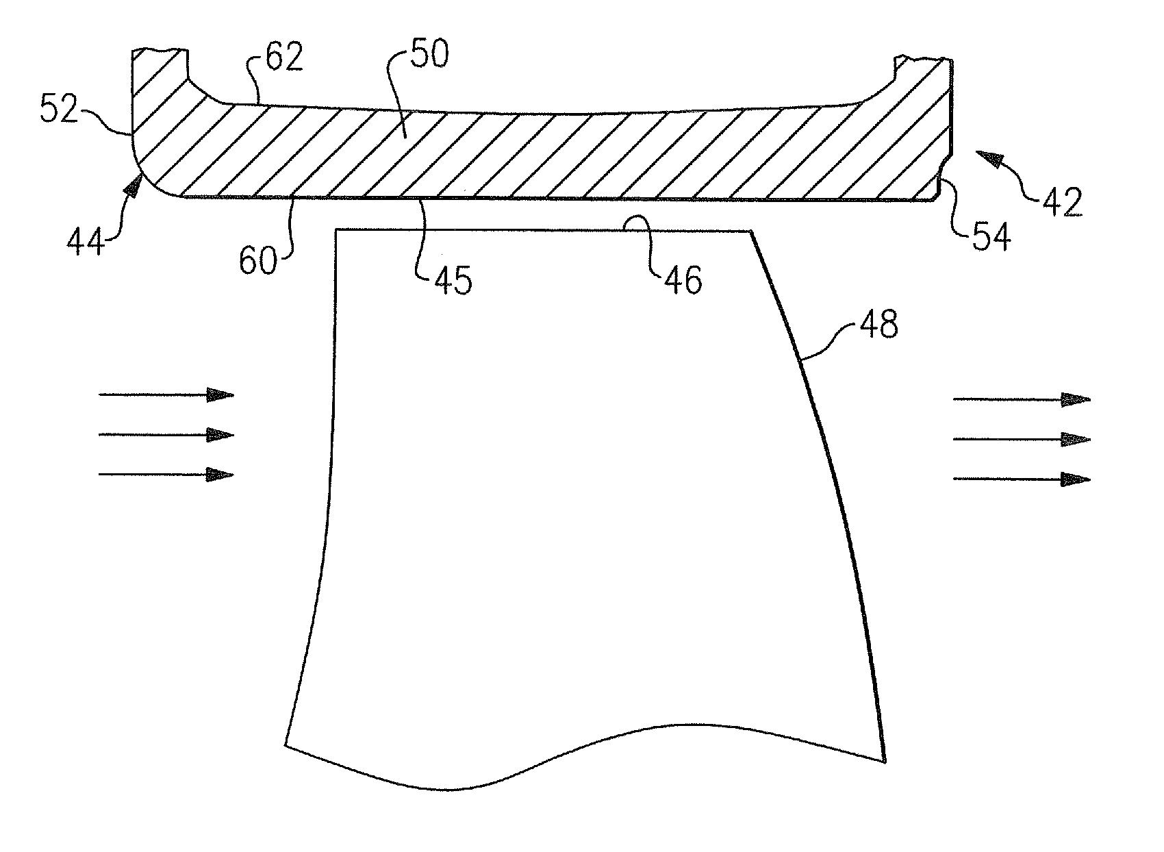
[0010]In an embodiment, the second metal alloy is deposited in a recess formed in the body having a circumferential expanse that extends across the full circumferential expanse of the inwardly facing side of the body and a longitudinal expanse that extends across a central region of the inwardly facing side of the body to encompass at least the hot rub strip region on the inwardly facing side of the body. The BOAS segment in accord with the invention may be an original equipment manufacture or a repaired BOAS segment. In an embodiment of an original equipment manufacture BOAS segment, the deposit of the second metal alloy may extend across the full circumferential expanse and the full longitudinal expanse of the inwardly facing side of the body of the BOAS segment. The formation of cracks due to thermal mechanical fatigue in a BOAS segment for a gas turbine engine is minimized, if not eliminated, through a unique construction of the BOAS segment, whether original equipment manufacture or a repaired blade outer air seal.

Problems solved by technology

Hot gas flowing between the blade tips and the blade outer air seal bypasses the turbine, thereby reducing turbine efficiency.
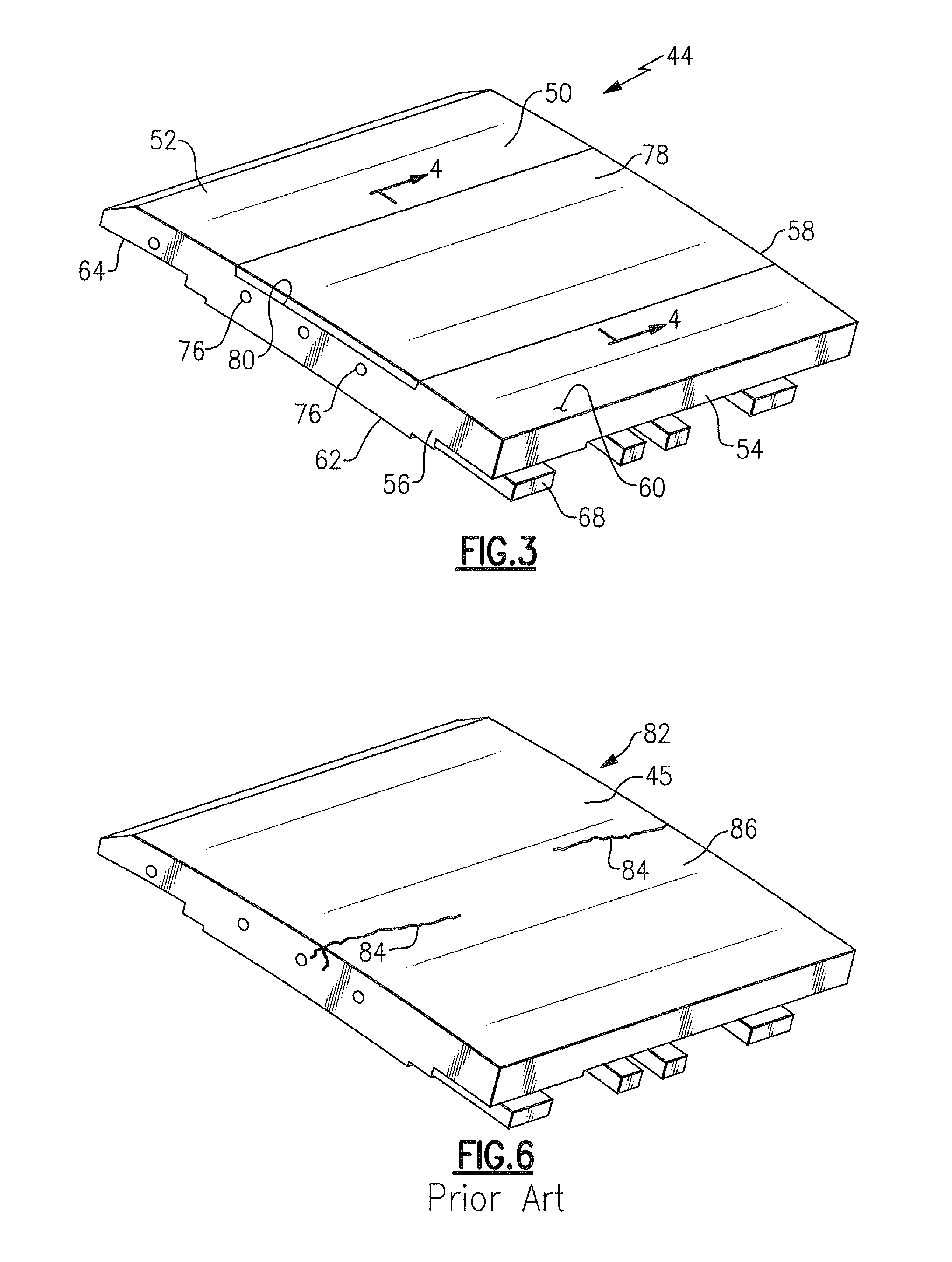
Despite the cooling of the BOAS segments, in the harsh thermal environment to which the blade outer air seal is exposed, particularly in the high pressure turbine section located immediately aft of the combustion chamber, the BOAS segments may over repeated thermal cycles of exposure to the hot gases crack due thermal mechanical fatigue.
After repeated thermal cycling, the residual tensile stresses can form thermal mechanical fatigue cracks on the radially inboard surface of the BOAS segment, which may necessitate premature removal of the engine from service to remove and replace cracked and damaged segments of the blade outer air seal.

Method used


Image

  • Blade outer air seal and repair method
  • Blade outer air seal and repair method
  • Blade outer air seal and repair method

Examples


Embodiment Construction

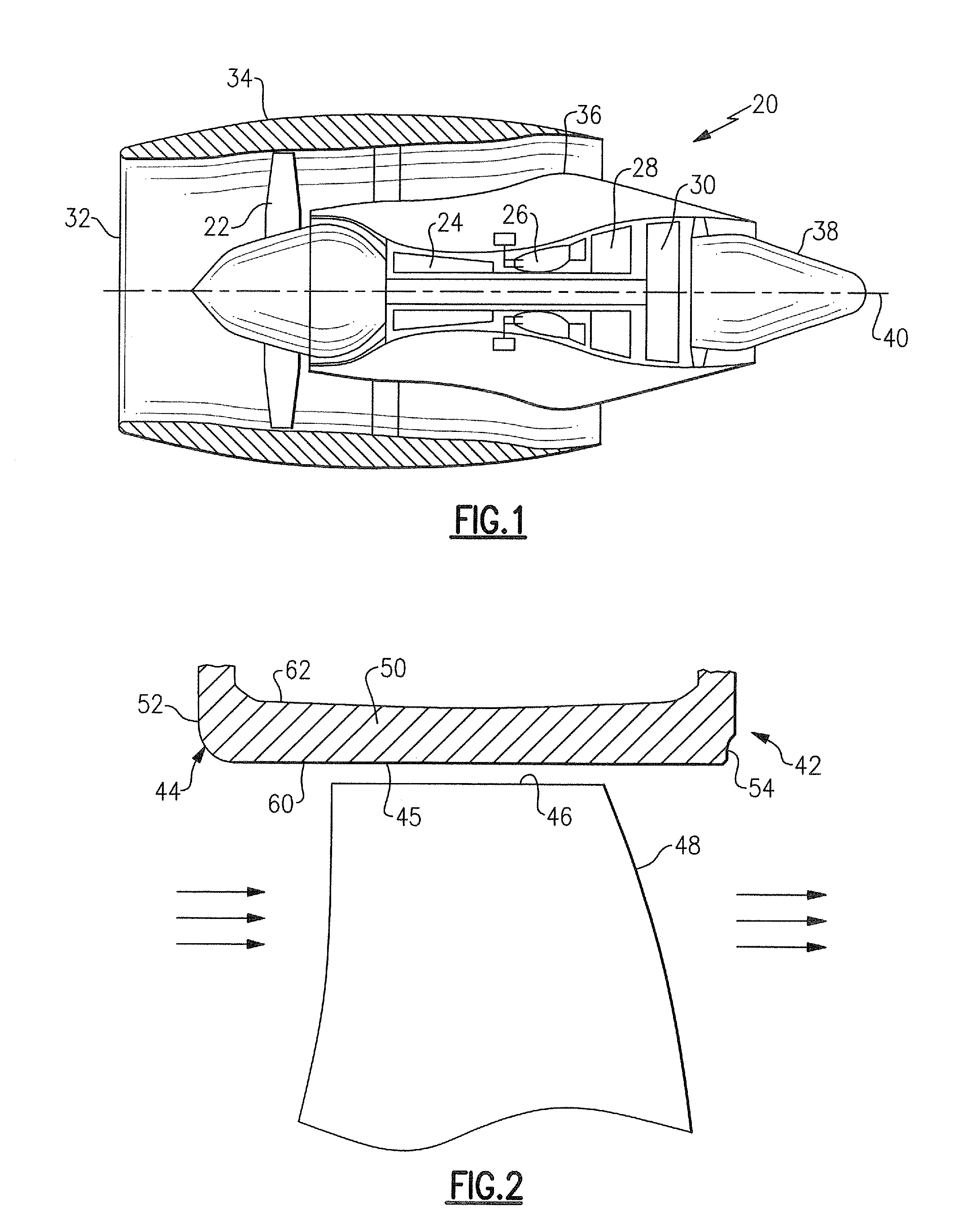
[0021]Referring now in FIG. 1, there is shown an exemplary embodiment of a turbofan gas turbine engine, designated generally as 20, that includes, from fore-to-aft, a fan 22, a compressor module 24, a combustor module 26, a high pressure turbine module 28, a low pressure turbine module 30 and an exhaust nozzle. A nacelle forms a housing or wrap that surrounds the gas turbine engine 20 to provide an aerodynamic housing about gas turbine engine. In the turbofan gas turbine engine 20 depicted in the drawings, the nacelle includes, from fore to aft, the engine inlet 32, the fan cowl 34, the engine core cowl 36 and the primary exhaust nozzle 38. The high pressure turbine module 28 and the low pressure turbine module 30 are disposed within the engine core cowling 36 aft of the combustor module 26 and include a plurality of turbine stages coaxially disposed in an axial array about a central longitudinal axis 40. It is to be understood that the BOAS segment and the method for restoration of...


PUM

PropertyMeasurementUnit
Temperatureaaaaaaaaaa
Fractionaaaaaaaaaa
Fractionaaaaaaaaaa

Abstract

An article of manufacture has a body formed in part of a first metal alloy and in part of a second metal alloy, the second metal alloy having a thermal coefficient of expansion that is less than the thermal coefficient of expansion of the first metal alloy. A BOAS segment for a gas turbine engine is disclosed wherein the formation of cracks due to thermal mechanical fatigue in the body of the disclosed BOAS segment is minimized, if not eliminated, through a unique construction of the disclosed BOAS segment, whether original equipment manufacture or a repaired blade outer air seal. A method for manufacture of a BOAS segment and a method for modifying a BOAS segment are disclosed.

Description

FIELD OF THE INVENTION[0001]This invention relates generally to gas turbine engines and, more particularly, to a blade outer air seal for a gas turbine engine and a method for restoration of a blade outer air seal for a gas turbine engine.BACKGROUND OF THE INVENTION[0002]Gas turbine engines, such as those used to power modern commercial aircraft or in industrial applications, include a compressor for pressurizing a supply of air, a combustor for burning a hydrocarbon fuel in the presence of the pressurized air, and a turbine for extracting energy from the resultant combustion gases. Generally, the compressor, combustor and turbine are disposed about a central engine axis with the compressor disposed axially upstream of the combustor and the turbine disposed axially downstream of the combustor.[0003]In operation of a gas turbine engine, fuel is combusted in the combustor in compressed air from the compressor thereby generating high-temperature combustion exhaust gases, which pass thr...

Claims


Application Information

Patent Timeline
IPC IPC(8): F04D29/08B23P6/00
CPCF01D9/04Y02T50/67F05D2300/50212F01D11/12Y10T29/49318F05D2230/80F05D2240/11Y10T29/49238Y10T29/4932F05D2230/30Y02T50/60
Inventor BELANGER, PHILIP R.THOLEN, SUSAN M.
Owner RAYTHEON TECH CORP
Learn More