Compressed air plenum for a gas turbine engine

Inactive Publication Date: 2012-02-09
SIEMENS ENERGY INC
View PDF13 Cites 14 Cited by
  • Summary
  • Abstract
  • Description
  • Claims
  • Application Information

AI Technical Summary

Benefits of technology

[0003]This invention is directed to a compressed air supply system for routing compressed air from a compressor to at least one combustor of a gas turbine engine. The compressed air supply system may be formed from one or more plenums having an upstream end in fluid communication with an inner chamber of the compressor in which air is compressed and having a downstream end in fluid communication with the at least one combustor. Channeling compressed air

Problems solved by technology

However, the compressor exit temperature is

Method used


Image

  • Compressed air plenum for a gas turbine engine
  • Compressed air plenum for a gas turbine engine
  • Compressed air plenum for a gas turbine engine

Examples


Embodiment Construction

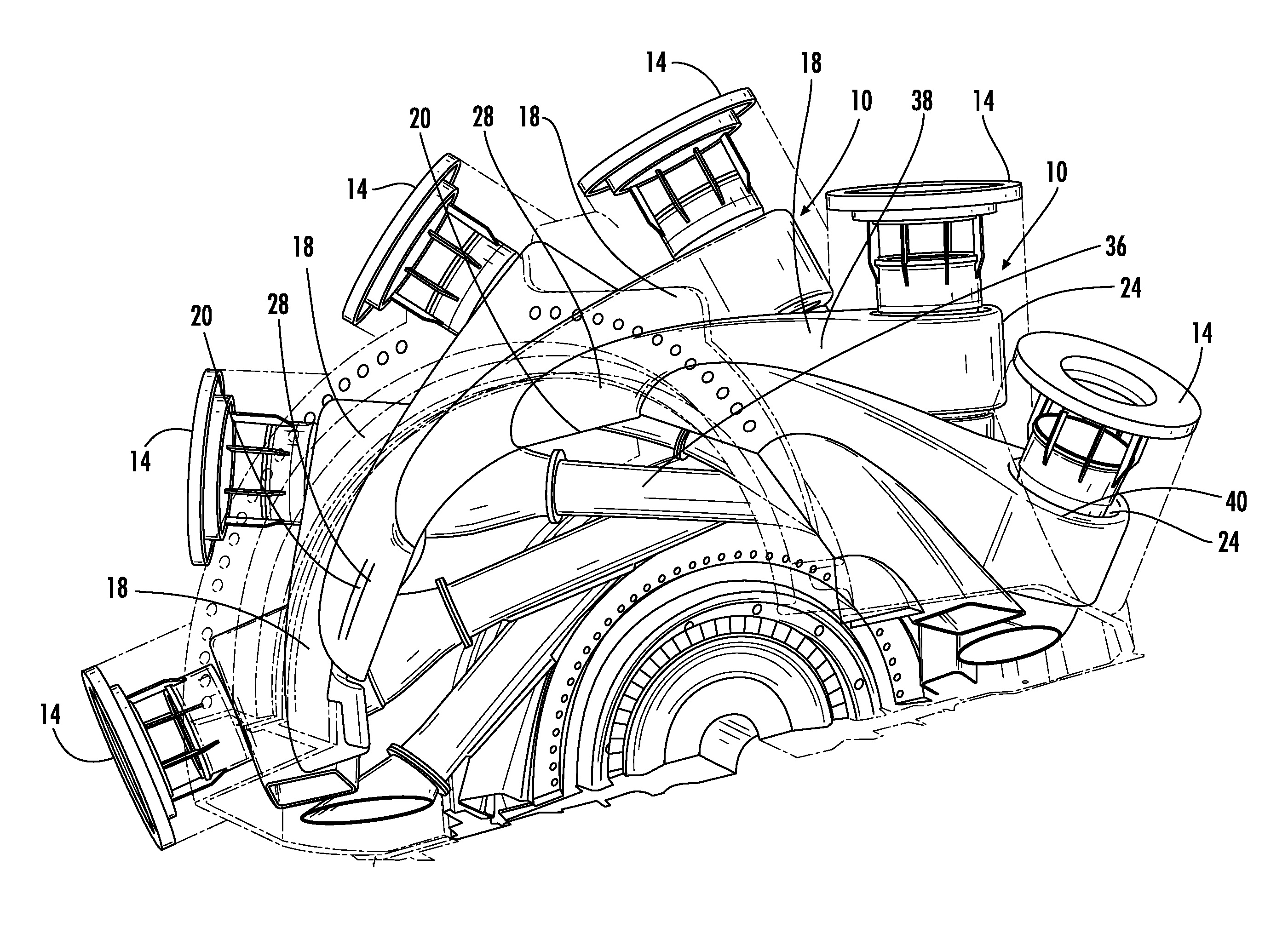
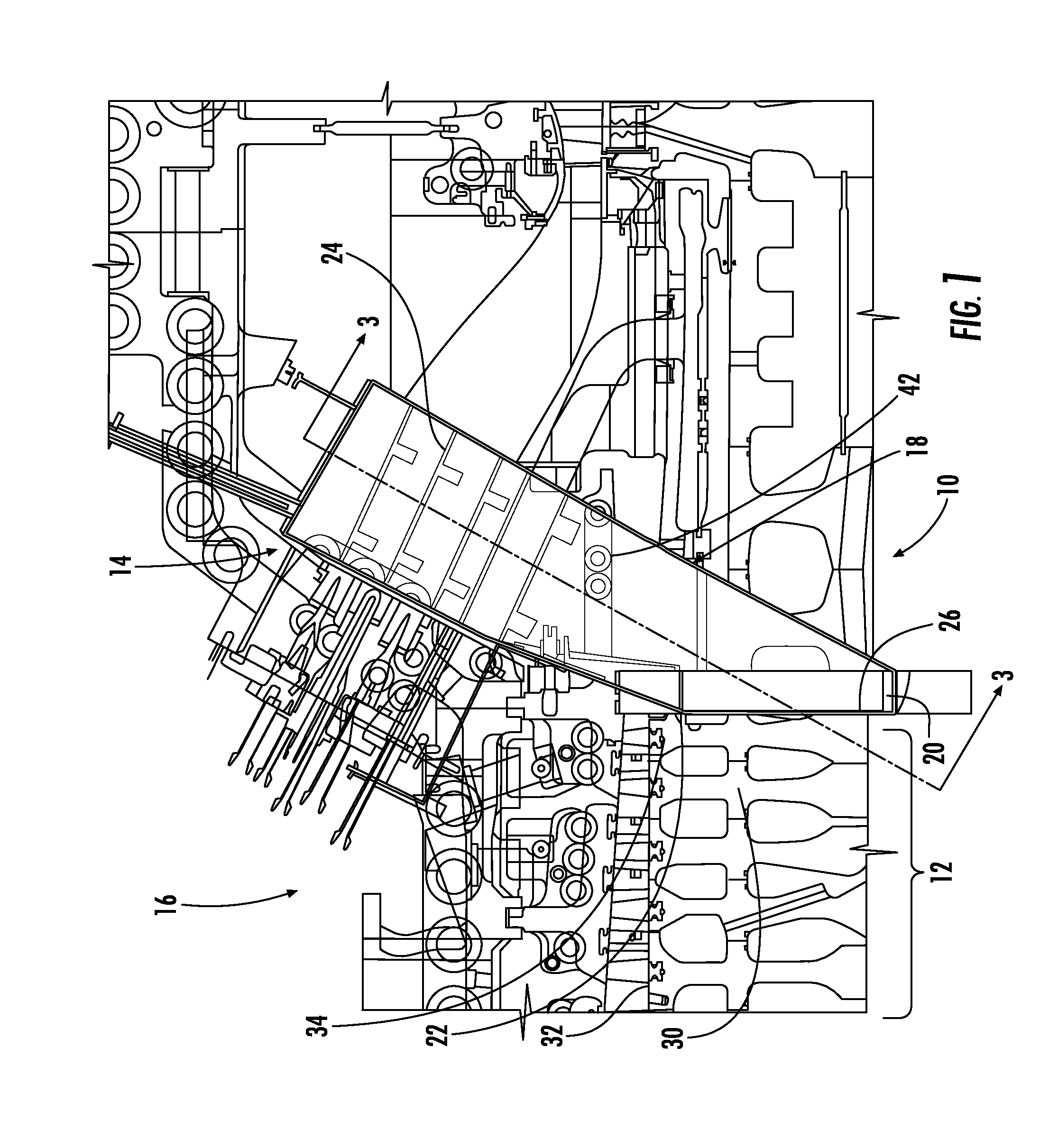
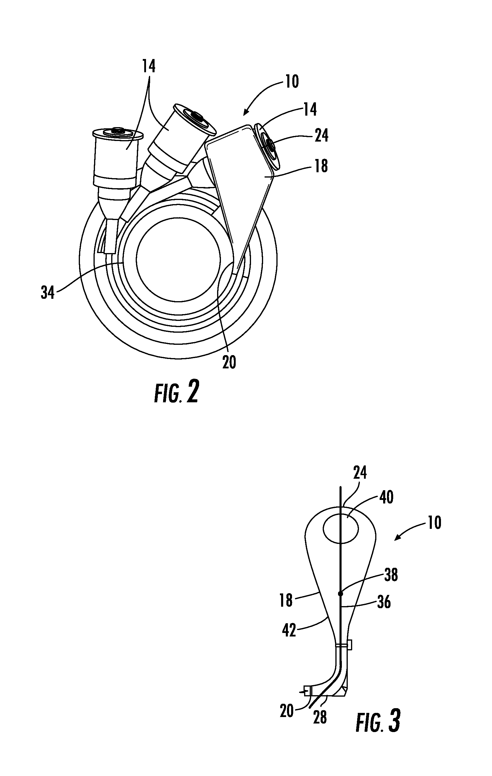
[0019]As shown in FIGS. 1-5, this invention is directed to a compressed air supply system 10 for routing compressed air from a compressor 12 to at least one combustor 14 of a gas turbine engine 16. The compressed air supply system 10 may be formed from one or more plenums 18 having an upstream end 20 in fluid communication with an inner chamber 22 of the compressor 12 in which air is compressed and having a downstream end 24 in fluid communication with the at least one combustor 14. Channeling compressed air through the plenum 18 reduces damage to other components of the turbine engine 16 by confining the compressed air within the plenum 18. The upstream end of the plenum 18 may be sealed to at least a portion of the compressor 12, and the downstream end 24 of the plenum 18 may be sealed to at least a portion of one or more combustors 14 such that the pressure of the compressed air within the plenum 18 may be controlled separately from other air within the shell of the turbine engin...


PUM


Abstract

A compressed air supply system for routing compressed air from a compressor to at least one combustor of a gas turbine engine is disclosed. The compressed air supply system may be formed from one or more plenums having an upstream end in fluid communication with an inner chamber of the compressor in which air is compressed and having a downstream end in fluid communication with the at least one combustor. Channeling compressed air through the plenum reduces damage to other components by confining the compressed air within the plenum. An upstream end of the plenum may be sealed to at least a portion of the compressor, and a downstream end of the plenum may be sealed to at least a portion of one or more combustors.

Description

FIELD OF THE INVENTION[0001]This invention is directed generally to gas turbine engines, and more particularly to components useful for routing compressed air from compressors to a combustors of gas turbine engines.BACKGROUND OF THE INVENTION[0002]Typically, gas turbine engines include a compressor for compressing air, a combustor for mixing the compressed air with fuel and igniting the mixture, and a turbine blade assembly for producing power. Compressed air is exhausted from an exhaust opening in the compressor into the shell of the turbine engine wherein the compressed air diffuses into a mid-frame cavity and undergoes turbulent flow around the hardware before finding the inlet to the combustor. In such a configuration, all of the components forming the turbine engine that are contained within the shell are exposed to pressurized, hot air. However, the compressor exit temperature is often too high for the steel casing material.SUMMARY OF THE INVENTION[0003]This invention is direc...

Claims


Application Information

Patent Timeline
IPC IPC(8): F02C7/00
CPCF01D9/023F05D2260/96F02C7/00
Inventor CHARRON, RICHARD
Owner SIEMENS ENERGY INC
Why Eureka
Try Eureka