

Electrospinning nozzle
- Summary
- Abstract
- Description
- Claims
- Application Information
AI Technical Summary
Benefits of technology
Problems solved by technology
Method used
Image

Examples
first embodiment
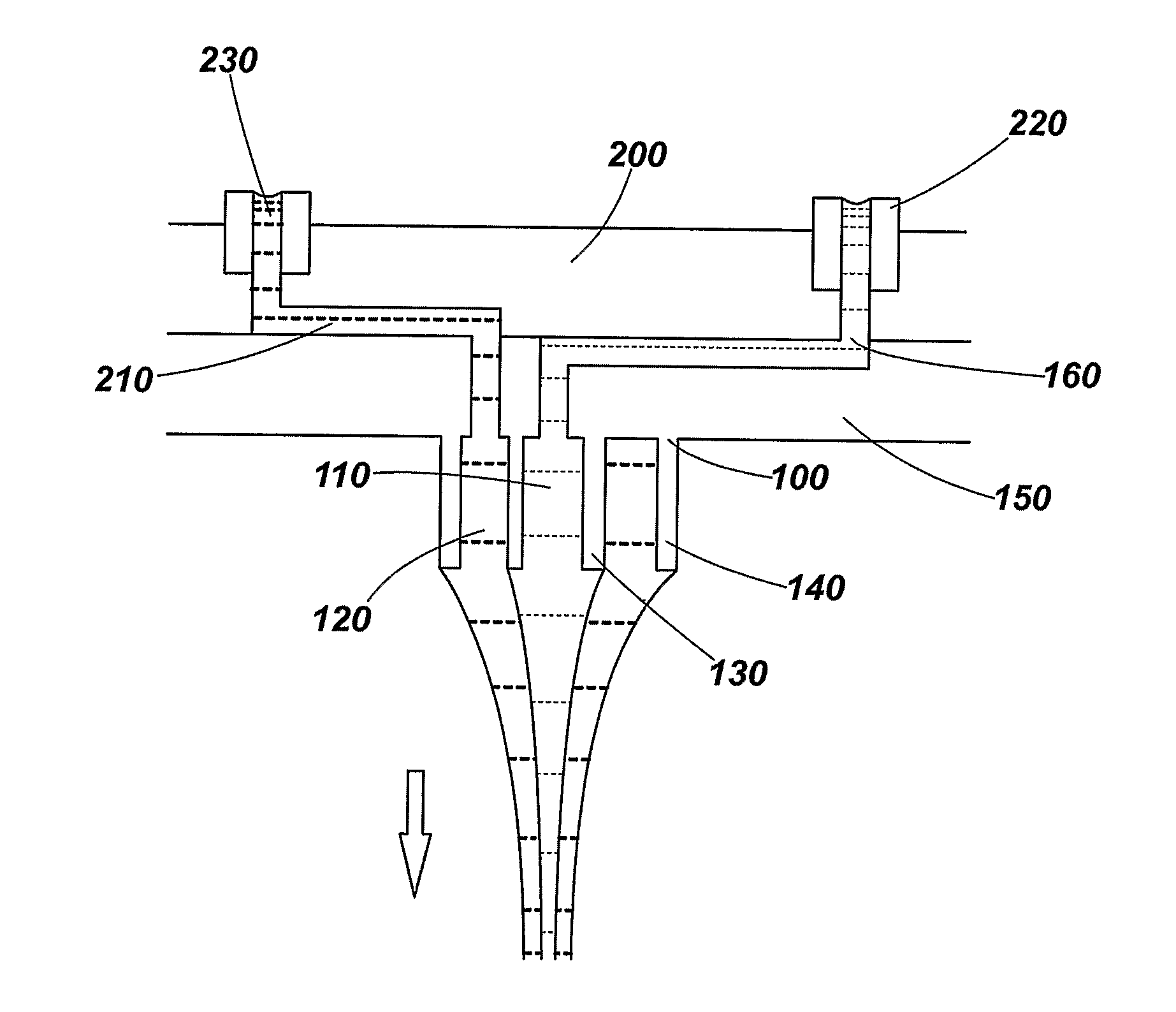
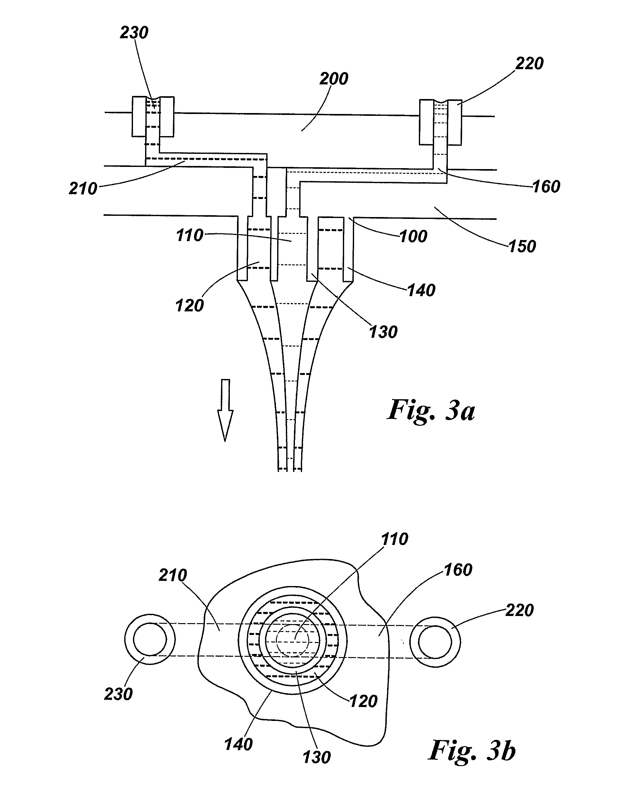
[0043]FIG. 3a shows an electrospinning nozzle 100 and manifold 200 in cross-section. The nozzle 100 comprises a plurality of ducts 110, 120 through which fluid flows. The ducts shown in FIG. 3 comprise a cylindrical bore 110 which is surrounded by an annular aperture 120. The bore 110 and inner edge of the annular aperture 120 are bounded by a first tubular wall 130. The annular aperture 120 is bounded at its outer edge by a second tubular wall 140. As shown in FIG. 3a the tubular walls 130, 140 protrude from a substrate 150. The space formed by the bore 110 provides a channel through which a first fluid can flow. The bore 110 is generally a circular bore, although other shapes can be used. Similarly, other shapes for the aperture 120 can be used. If other shapes are used for the bore 110 and the outer annular aperture 120, surface tension will cause a Taylor cone formed at the end of the nozzle to have a circular cross-section. Hence, for more reliable cone formation, circular and ...
second embodiment
[0051]FIG. 4 shows the nozzle in which three separate ducts for supplying different fluids are provided. The three ducts comprise a central bore 110, a first annular aperture 120 and a second annular aperture 310. The bore, first and second apertures have a common centre located at the centre of the bore 110. The bore 110 and first annular aperture 120 are the same as the bore and annular aperture of FIG. 3a and hence like reference numerals are used. The openings at the ends of the bore and apertures are sometimes referred to as interspaces.
[0052]This embodiment allows even more complex nanofibres to be produced. For example, each interspace may be used to supply a different fluid and therefore the produced fibre may have a core, inner shell and outer shell, each of which is made of a different material.
[0053]Around some of the nozzle surfaces may be provided a hydrophobic conductive coating 320, as shown in FIG. 4. This coating is provided on the underside of the substrate 150 and...
PUM
| Property | Measurement | Unit |
|---|---|---|
| Pressure | aaaaa | aaaaa |
| Diameter | aaaaa | aaaaa |
| Hydrophilicity | aaaaa | aaaaa |
Abstract
Description
Claims
Application Information