
Photochemical tissue bonding

a tissue bonding and photochemical technology, applied in the field of photochemical tissue bonding, can solve the problems of unnatural response of the host to foreign material, undesirable characteristics of the stent device described above, and impair the natural biological function of the luminal anatomic structur

Inactive Publication Date: 2012-02-09
THE GENERAL HOSPITAL CORP
View PDF5 Cites 14 Cited by
  • Summary
  • Abstract
  • Description
  • Claims
  • Application Information

AI Technical Summary

Benefits of technology

[0013]Certain exemplary embodiments of the instant invention can provide an exemplary use of photoactivatable biological membrane (PAM) as a luminal covering material. Other exemplary embodiments of the instant invention can provide exemplary methods for covering, repairing, and maintaining the patency of an anatomic structure, for example a luminal anatomic structure, using a photoactivatable biological membrane.
[0015]A further embodiment of the present invention relates to a method for stabilizing a luminal anatomical structure, the method comprising: contacting a biological membrane with a photosensitizer agent; deploying the biological membrane to the luminal anatomical structure in need of stabilization; applying electromagnetic energy to the biological membrane-photosensitizer complex in a manner effective to bond the tissue; thereby stabilizing a luminal anatomical structure.
[0016]Still further another embodiment of the present invention relates to a method for treating or preventing an atherosclerotic plaque, the method comprising: identifying an atherosclerotic plaque; contacting a biological membrane with a photosensitizer agent; deploying the biological membrane to the atherosclerotic plaque; applying electromagnetic energy to the biological membrane-photosensitizer complex in a manner effective to bond the tissue; thereby treating or preventing an atherosclerotic plaque.
[0038]In addition, prior to an application of the tissue structure to the luminal anatomical structure, the tissue structure is modified to improve healing of the luminal anatomical structure.

Problems solved by technology

Stent devices as described above may have undesirable characteristics.
For example, even though the stents are typically comprised of inert materials, they are not commonly biological materials and the host responds to the foreign material unnaturally.
Damage to the luminal anatomic structure causes an unnatural healing response to the stent, which can result in subsequent closing or restenosis of the luminal structure or improper re-endothelialization of epithelialization of the stent surface, which impairs the natural biological function of the luminal anatomic structure.
Additionally, owing to the mechanical properties of the stent, the stent should usually comprise a circular cylindrical topology, which can require coverage of areas of the anatomical structure that may not need covering, thereby increasing the risk of adverse consequences.
Furthermore, this required circular cylindrical topology may not be appropriate if the luminal structure does not share the diameter or same circularly cylindrical topology as the stent.
This topology mismatch can occur frequently and malapposition of the stent struts results.
Malapposition further causes the host to respond to the stent in an unnatural manner, further increasing the likelihood of future adverse complications.
There are circumstances in medicine however, when maintaining luminal patency is not the primary function of the stent.
As a result, extrinsic or intrinsic mechanical forces can cause the cap to break or rupture, exposing the thrombogenic lipid to blood.
However, the nature of common stent deployment mechanisms is destructive of the luminal structure, thereby causing rupture upon deployment.
This iatrogenic rupture causes emboli to be sent downstream, which lodge in arteries, further causing infarction.
Later, malapposition and tissue alteration causes unnatural biological response to the stent that can result in improper endothelialization of the stent and restenosis.
Current stents also cause difficulties when inserted into the artery owing to the thrombogenic nature of the stent strut surface that may cause a thrombus to form, resulting in occlusion of the lumen.

Method used


Image

  • Photochemical tissue bonding
  • Photochemical tissue bonding
  • Photochemical tissue bonding

Examples


example 1

Photoactivatable Biological Membrane (PAM) Device

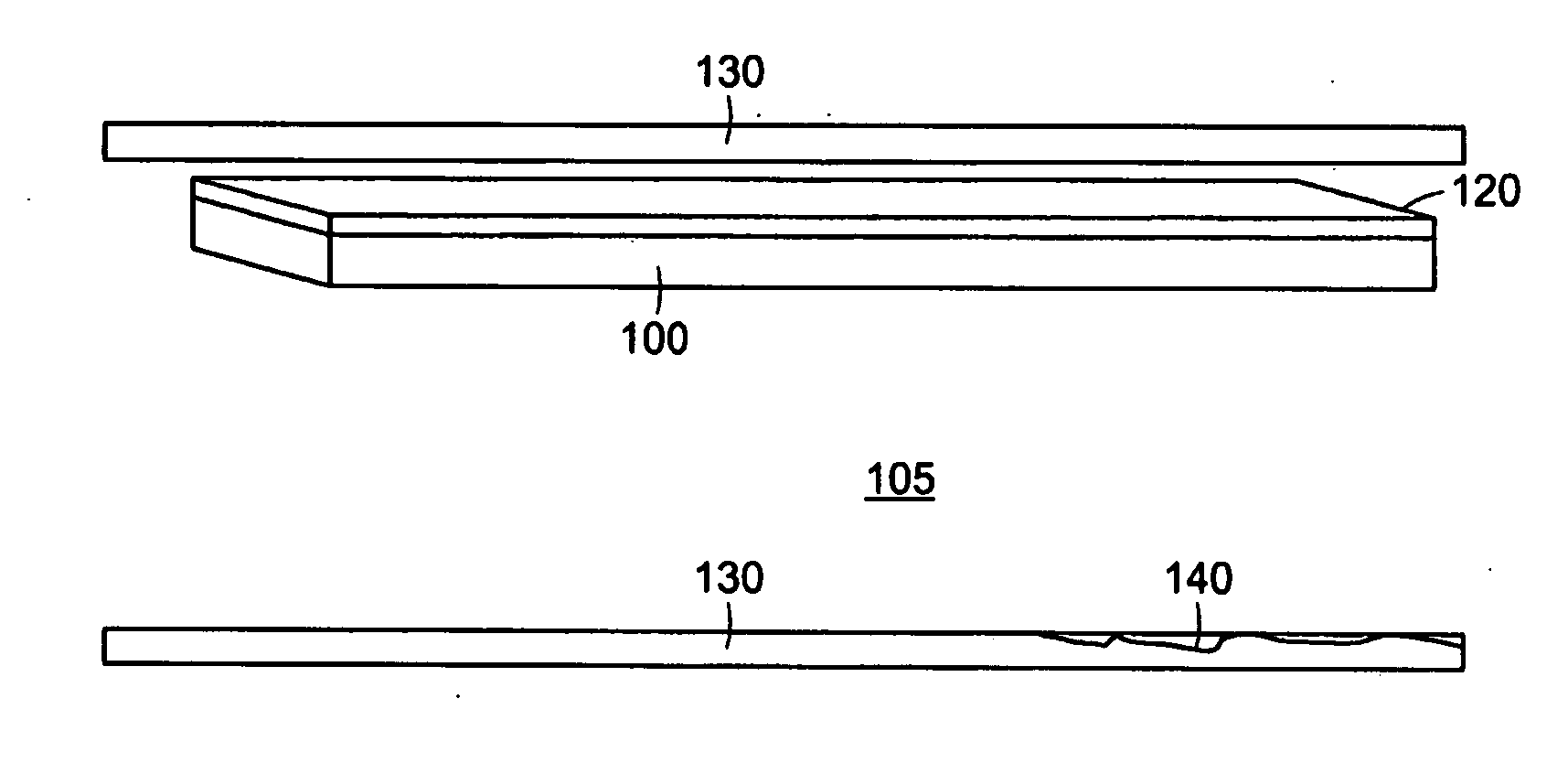
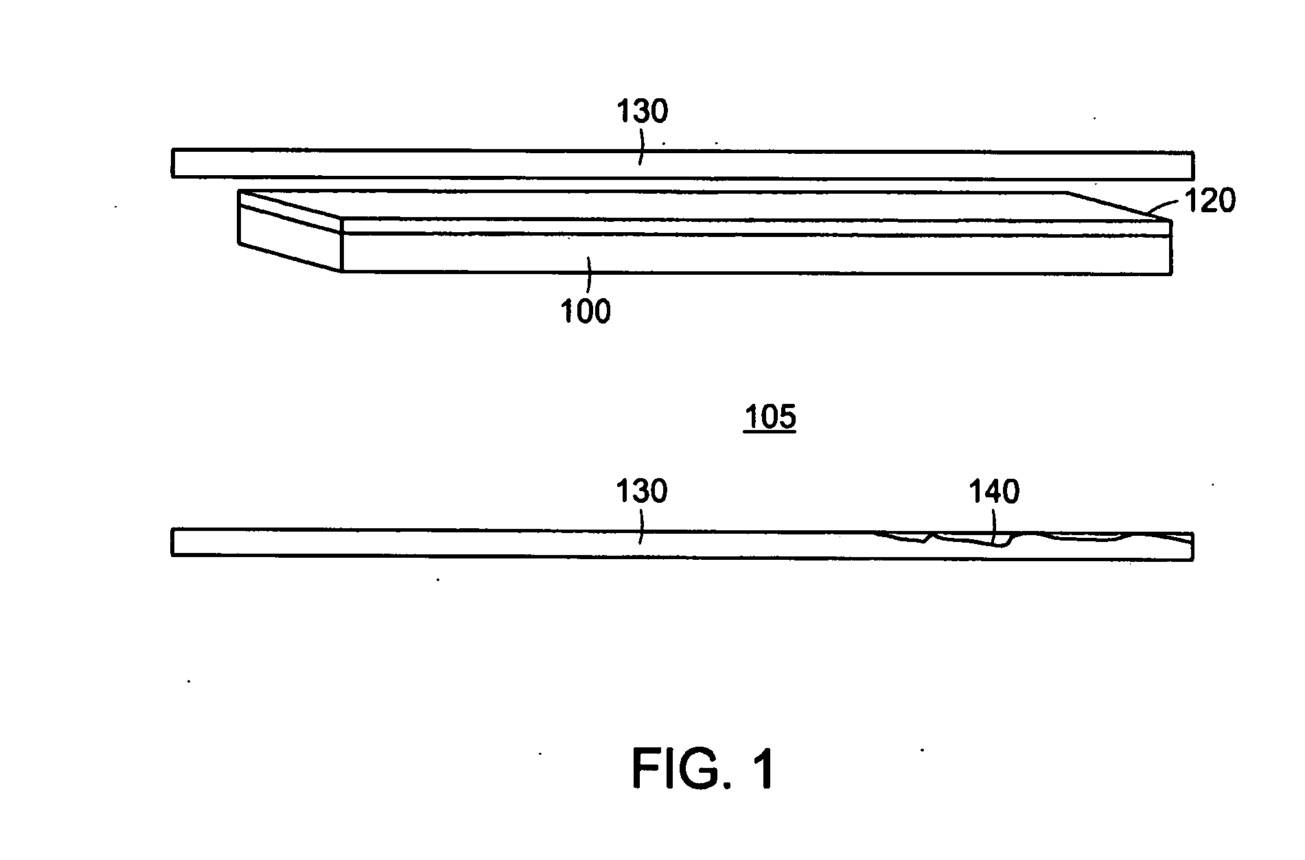
[0102]FIG. 1 depicts a small portion of an exemplary PAM device. The exemplary PAM device comprises a biological membrane 100, such as an amniotic membrane, which may be taken from the amnion of an animal, such as cow, pig, sheep, or the like, or alternatively in an exemplary embodiment from a human pregnancy, post-partum. The biologic membrane is constructed through synthetic chemistry means. In a preferred embodiment the biological membrane contains an epithelial surface, basement membrane, and connective tissue layers. The biological membrane, which in certain examples can preferably be an amniotic membrane, is coated or comprised there through of a photoactivatable dye 120. In certain preferred embodiments the dye is Rose Bengal. Alternatively, other photoactivatable dyes, including riboflavin-5-phosphate and methylene blue may be used. Photoactivatable dyes Rose Bengal, riboflavin-5-phosphate and methylene blue are typically acti...

example 2

Configuring the Exemplary PAM Device

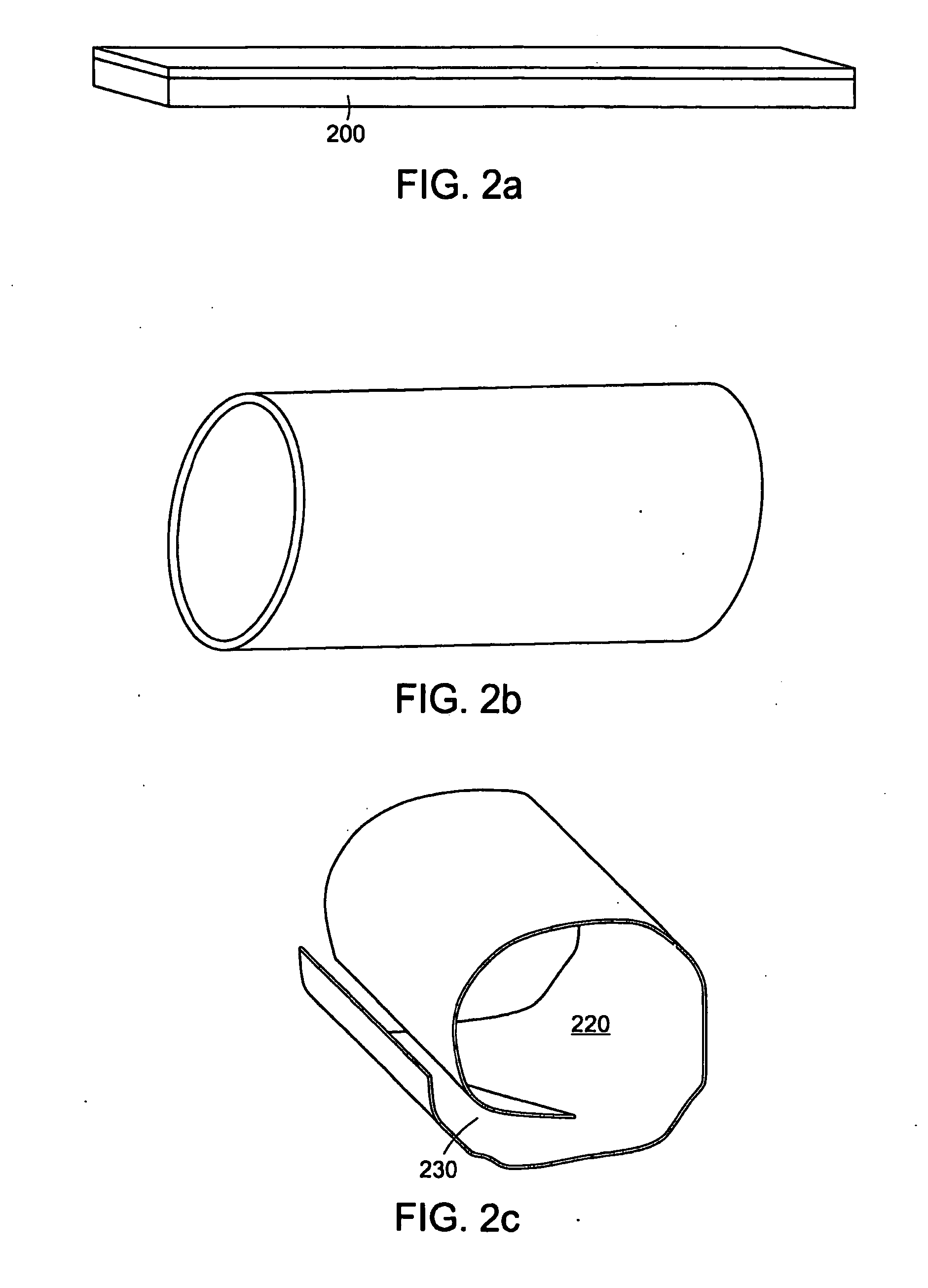
[0105]FIG. 2 is a diagram of different exemplary PAM device configurations. These exemplary configurations can comprise different topologies of the PAM device that are formed prior to deployment, during, or after deployment to conform to and / or alter the topology of the luminal anatomic structure. FIG. 2a depicts an exemplary PAM device configuration that comprises a sheet of PAM 200. This configuration in one exemplary embodiment can be appropriate for imparting stability to one portion of the luminal anatomical structure. In another embodiment this topology may be used to repair a defect in at least one portion of the luminal anatomic structure. In yet another exemplary embodiment, this configuration may be used to treat, repair, or cover only the portion of the luminal anatomic structure that requires alteration while leaving the remainder of the luminal anatomic structure intact. FIG. 2b depicts another exemplary PAM device configuration where...

example 3

Modifying the Luminal Surface for the PAM Device

[0108]One aspect of the exemplary PAM device is that when it is deployed, it may be prevented or limited to further substantially move within, across, or along the luminal surface of the luminal anatomic structure. In part, motion is prohibited by the affixation characteristics of the photoactivatable dye. Affixation characteristics of the PAM device

[0109]with respect to the luminal surface of the luminal anatomic structure may be further enhanced by a modification of the luminal surface. In one exemplary embodiment, this may be accomplished by at least one of partially scraping or abrading the epithelial or endothelial cell layer of the luminal surface of the luminal anatomic structure 140. In another exemplary embodiment, the way for enhancing the anchoring properties of the PAM device include further enhancing the PAM device so that the edges of said PAM device become further affixed to the anatomic luminal structure. In one exempla...


PUM


Abstract

The exemplary embodiments of the present invention provides exemplary methods for adhering biological membranes to luminal anatomical structures using photosensitizing agents and electromagnetic energy. The exemplary embodiments of the present invention also provides method for stabilizing luminal anatomical structures. Further, exemplary embodiments of the present invention provide arrangements for coupling to a luminal anatomical structure.

Description

RELATED APPLICATIONS / PATENTS AND INCORPORATION BY REFERENCE[0001]This International application claims priority to U.S. Provisional Application No. 60 / 997,472, filed Oct. 3, 2007, the entire contents of which are incorporated herein by reference.[0002]The foregoing applications, and all documents cited therein and all documents cited or referenced therein, and all documents cited or referenced herein, including any U.S. or foreign patents or published patent applications, International patent applications, as well as, any non-patent literature references and any manufacturer's instructions, are hereby expressly incorporated herein by reference.GOVERNMENT SUPPORT[0003]Research supporting this application was supported by Department of Defense, Medical Free Electron Problem, Contract No. FA9550-04-1-0079. The government may have certain rights in the invention.FIELD OF THE INVENTION[0004]The present invention relates to a field of photochemical tissue bonding, and in particular to met...

Claims


Application Information

Patent Timeline
IPC IPC(8): A61B18/18A61F2/06A61F2/82
CPCA61F2/062A61F2/82A61L27/3604A61L27/50A61L31/005A61L31/14A61N5/0601A61N5/062
Inventor TEARNEY, GUILLERMOBOUMA, BRETTREDMOND, ROBERT W.KOCHEVAR, IRENE E.
Owner THE GENERAL HOSPITAL CORP
Learn More