Angle detection apparatus and position detection apparatus

a detection apparatus and position technology, applied in special purpose recording/indication apparatus, measurement devices, instruments, etc., can solve the problems of inability to measure the rotation angle or movement with high accuracy, unstable signal, etc., to improve the output linearity of magnetic sensors, limited rotation angle or position range, and high accuracy

Inactive Publication Date: 2012-02-16
HITACHI METALS LTD
View PDF6 Cites 43 Cited by
  • Summary
  • Abstract
  • Description
  • Claims
  • Application Information

AI Technical Summary

Benefits of technology

[0006]Accordingly, an object of the present invention is to provide an apparatus with improved output linearity of a magnetic sensor in a l

Problems solved by technology

Though the potentiometer system has a simple circuit, its signal is unstable because of the change of the sliding part with time.
However, this angle sensor det

Method used


Image

  • Angle detection apparatus and position detection apparatus
  • Angle detection apparatus and position detection apparatus
  • Angle detection apparatus and position detection apparatus

Examples


reference example 1

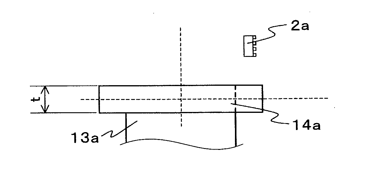
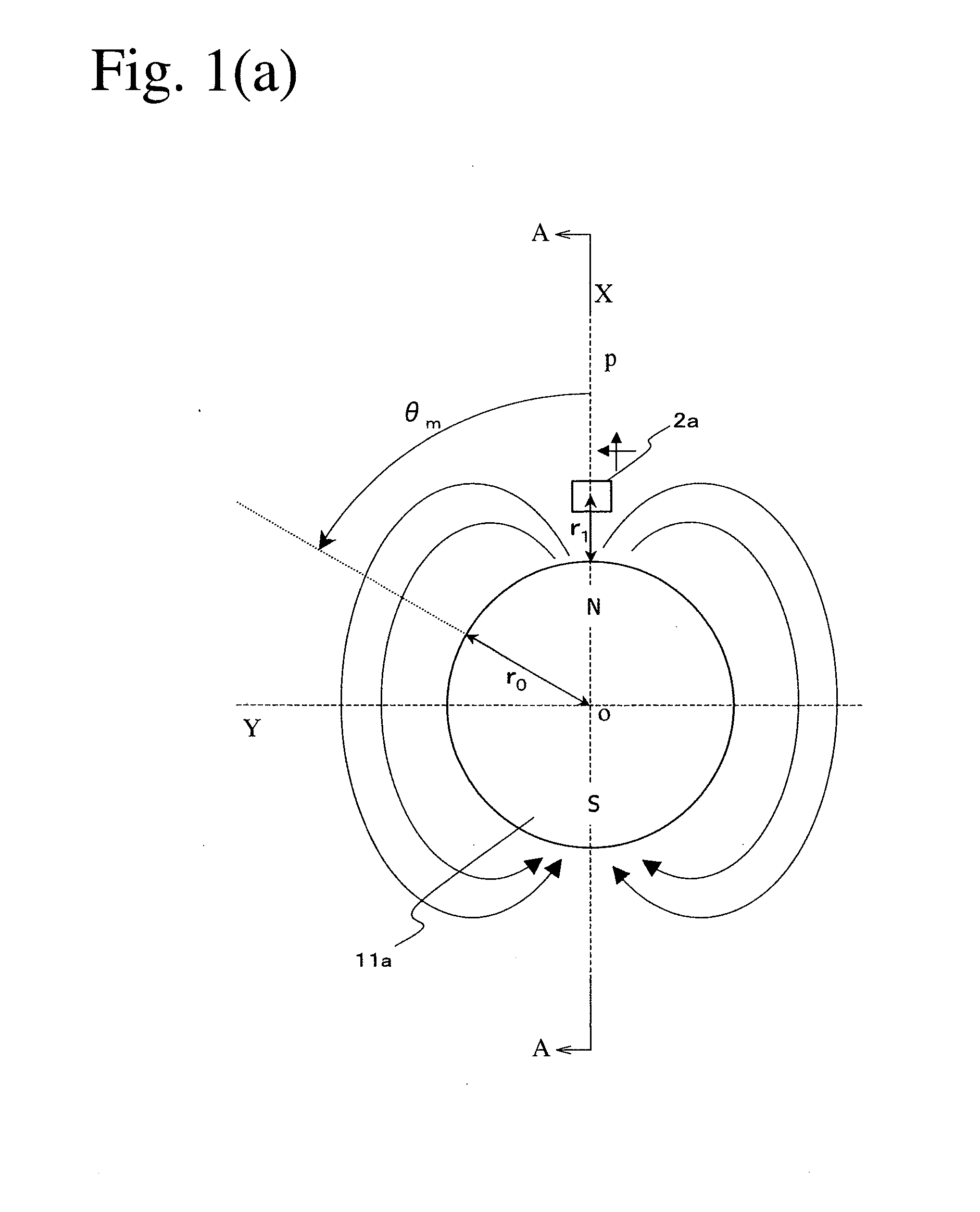
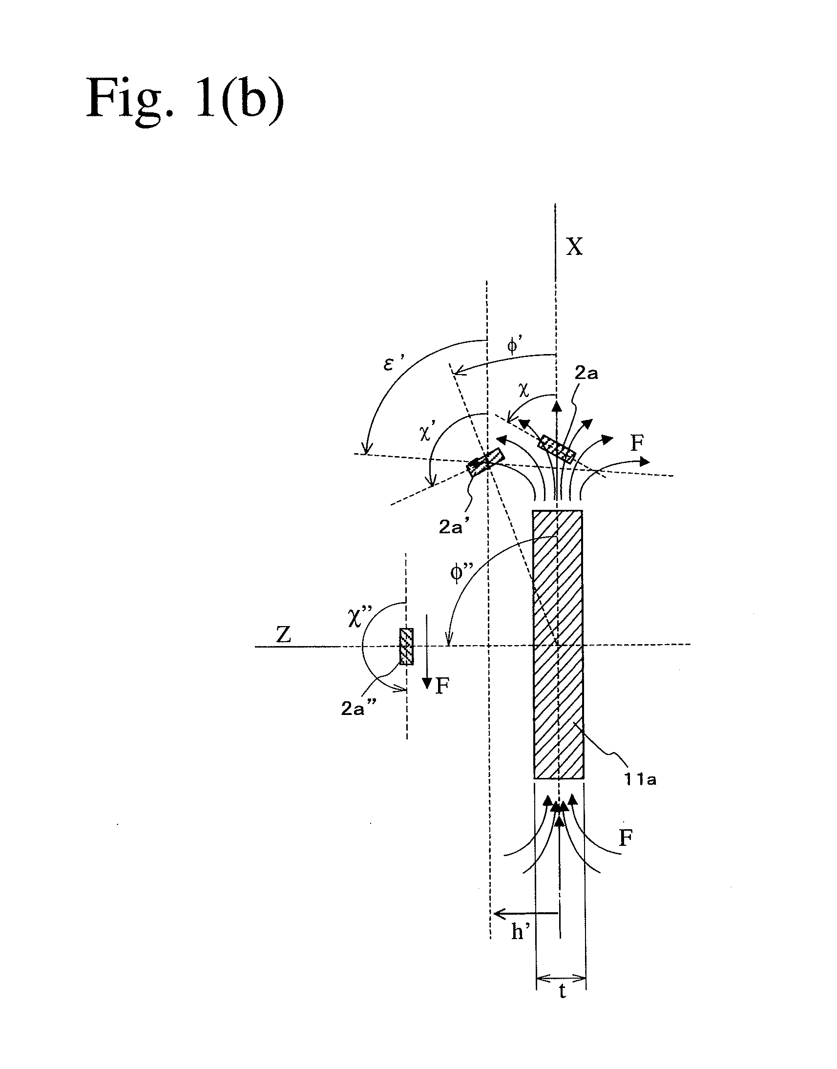
[0101]As shown in FIGS. 3(a) and 3(b), in a coordinate system (X, Y, Z) whose origin is a center O of the permanent magnet 11a, the magnetic sensor 2a shown in FIGS. 2(a)-2(c), which has a structure having bridge-connected spin-valve, giant-magnetoresistive devices, is arranged near a periphery (X, 0, 0) of the permanent magnet 11a. In the magnetic sensor 2a, the magnetosensitive plane is perpendicular to the rotating shaft of the permanent magnet 11a, and the magnetization directions of the pinned layers are in parallel to the Y axis. Magnetic flux components BX, BY, BZ in the X, Y and Z directions generated when the permanent magnet 11a rotates by an angle θm are expressed by the formulae (1).

BX=m4πR3cosθm(2cos2φ-sin2φ)BY=-m4πR3sinθmBZ=m4πR3cosθm(3cosφ·sinφ),(1)

wherein m represents a magnetic moment approximating the permanent magnet 11a, θm represents the rotation angle of the permanent magnet 11a, and φ represents an angle between a line connecting a center O of the permanent ma...

reference example 2

[0108]Reference Example 1 has shown a two-pole magnet providing an output having a period of an electric angle per a period of a mechanical angle, but it is advantageous to use a multi-pole magnet for detecting a small angle with high accuracy. FIGS. 8(a) and 8(b) show the angle detection apparatus of Reference Example 2. This angle detection apparatus comprises a magnet rotor comprising a 16-pole ring magnet 11b generating a polar-anisotropic magnetic field from the peripheral surface, and a shaft 13b fixed to a penetrating hole of the ring magnet 11b; and a magnetic sensor 2a arranged at a position separate from the peripheral surface of the ring magnet 11b. The radius r0 of the ring magnet 11b was 20 mm, the distance r1 from the peripheral surface of the ring magnet 11b to a center of the magnetic sensor 2a was 4 mm, the inner diameter r2 of the hole of the ring magnet 11b was 15 mm, and the thickness t of the ring magnet 11b in the Z direction (rotation axis direction of the mag...

reference example 3

[0110]FIGS. 10(a) and 10(b) show an angle detection apparatus comprising an 8-pole ring magnet 11b′ in Reference Example 3. r0=16 mm, r1=4 mm, r2=10 mm, and t=8 mm. Because K0 was 1.3, neither inclination nor axial displacement were conducted [h=0, and χ=0 in FIG. 5(b)]. As shown in FIG. 11(a), the magnetic sensor 2a output four periods of signals in response to a period of the rotation of the multi-pole ring magnet 11b′, which corresponded to the number of magnetic poles in the magnet; one of them was a substantially triangular wave. As shown in FIG. 11(b), evaluation using one period of this signal revealed that the angle detection error was within ±0.2° in a range of ±15°.


PUM


Abstract

An angle detection apparatus comprising a magnet rotor having a multi-pole segment magnet, and a magnetic sensor for detecting the direction of a magnetic flux generated from the multi-pole segment magnet; the multi-pole segment magnet having pluralities of magnetic poles along the rotation direction of the magnet rotor, the magnetic sensor comprising a magnetosensitive plane having pluralities of spin-valve, giant-magnetoresistive devices each having a pinned layer having a fixed magnetization direction and a free layer having a magnetization direction rotating in response to the magnetic flux direction; and the magnetic sensor being positioned relative to the magnet rotor, such that the magnetosensitive plane crosses the magnetic flux, with perpendicular magnetic flux density components having different amplitudes on the magnetosensitive plane.

Description

FIELD OF THE INVENTION[0001]The present invention relates to a small, high-accuracy angle or position detection apparatus having excellent output linearity.BACKGROUND OF THE INVENTION[0002]A throttle valve opening ratio sensor for gasoline engines uses a potentiometer system to detect the rotation angle (mechanical angle) of the throttle valve almost within 90°. The potentiometer system uses a brush attached to a rotating shaft of the valve and a fixed resistor, the brush rotating with the shaft sliding the resistor to provide changing resistance between the brush and an end of the resistor, from which the rotation angle of the valve is determined. Though the potentiometer system has a simple circuit, its signal is unstable because of the change of the sliding part with time. Thus proposed is a non-contact-type angle sensor for detecting the rotation angle of a shaft by measuring the direction of a magnetic flux generated from a magnet fixed to the rotating shaft by a magnetic senso...

Claims


Application Information

Patent Timeline
IPC IPC(8): G01B7/30
CPCG01D3/02G01D5/145G01D5/24476
Inventor AIMUTA, KYOHEIMITA, MASAHIRO
Owner HITACHI METALS LTD
Why Eureka
Try Eureka