Piezoelectric thin film, ink jet head, method of forming image by the ink jet head, angular velocity sensor, method of measuring angular velocity by the angular velocity sensor, piezoelectric generating element, and method of generating electric power using the piezoelectric generating element

a technology of piezoelectric generating element and ink jet head, which is applied in the direction of acceleration measurement using interia force, device material selection, and turn-sensitive devices, etc., can solve the problems of serious damage to the ecosystem and the environment, large amount of pzt, etc., and achieve high piezoelectric performance and low dielectric loss

Inactive Publication Date: 2012-02-16
PANASONIC CORP
View PDF3 Cites 24 Cited by
  • Summary
  • Abstract
  • Description
  • Claims
  • Application Information

AI Technical Summary

Benefits of technology

[0015]The present invention provides a lead-free piezoelectric thin film including a non-lead-containing (that is, lead-free) ferroelectric material and having low dielectric loss and high piezoelectric performance comparable to that of PZT, and a method of manufacturing the lead-free piezoelectric thin film.
[0016]The present invention also provides an ink jet head, an angular velocity sensor, and a piezoelectric generating element, each including the lead-free piezoelectric thin film.
[0017]The present invention further provides a method of forming an image by this ink jet head, a method of measuring an angular velocity by this angular velocity sensor, and a method of generating electric power using this piezoelectric generating element.

Problems solved by technology

PZT, however, contains a large amount of lead.
In recent years, there has been a growing concern that lead leached from waste may cause serious damage to the ecosystem and the environment.

Method used


Image

  • Piezoelectric thin film, ink jet head, method of forming image by the ink jet head, angular velocity sensor, method of measuring angular velocity by the angular velocity sensor, piezoelectric generating element, and method of generating electric power using the piezoelectric generating element
  • Piezoelectric thin film, ink jet head, method of forming image by the ink jet head, angular velocity sensor, method of measuring angular velocity by the angular velocity sensor, piezoelectric generating element, and method of generating electric power using the piezoelectric generating element
  • Piezoelectric thin film, ink jet head, method of forming image by the ink jet head, angular velocity sensor, method of measuring angular velocity by the angular velocity sensor, piezoelectric generating element, and method of generating electric power using the piezoelectric generating element

Examples


example 1

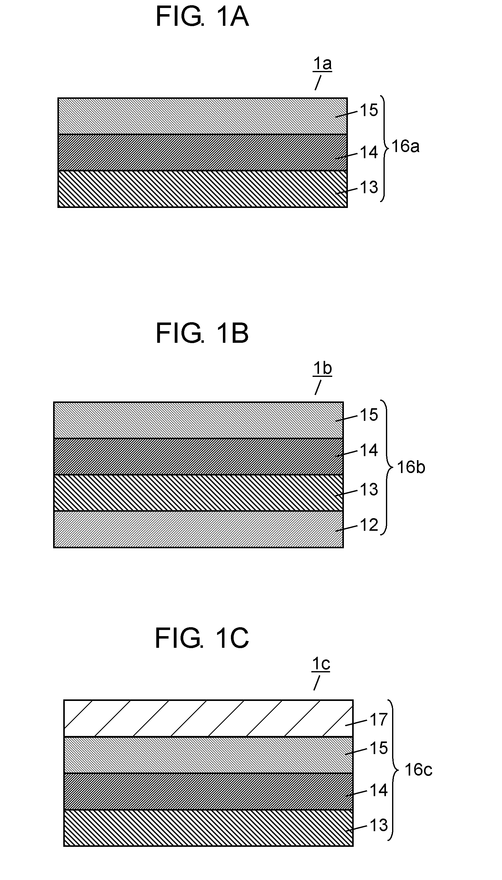
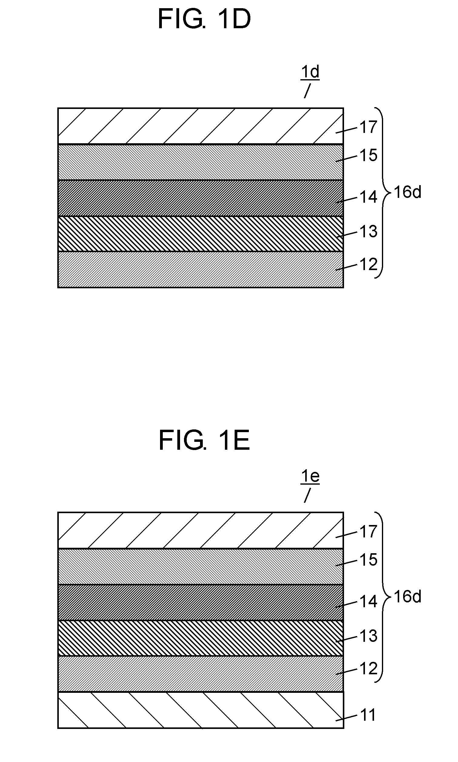
[0203]In Example 1, a piezoelectric thin film having a structure shown in FIG. 1E was fabricated. The piezoelectric thin film comprises the substrate 11, the metal electrode film 12, the LaNiO3 film 13, the (NaxBi0.5)TiO0.5x+2.75—BaTiO3 film 14 (x was equal to 0.35) (interface layer), the (Bi,Na,Ba)TiO3 film 15, and the conductive film 17 in this order. The fabrication procedure is as follows.

[0204]A Pt layer (with a thickness of 100 nm) having a (111) orientation was formed by RF magnetron sputtering on the surface, having a plane orientation of (100), of a monocrystalline Si substrate. The Pt layer corresponds to the metal electrode film 12. The Pt layer was formed using a metallic Pt target in an argon (Ar) gas atmosphere under the film formation conditions of an RF power of 15 W and a substrate temperature of 300 degree Celsius. To improve the adhesion between the monocrystalline Si substrate and the Pt layer, a Ti layer (with a thickness of 2.5 nm) was formed previously on the ...

example 2

[0216]An identical experiment to that of Example 1 was performed except that x was equal to 0.40.

[0217]The intensity of the (001) reflection peak according to Example 2 was 15,272 cps, which was a very high level. The measured half value width was very small.

example 3

[0218]An identical experiment to that of Example 1 was performed except that x was equal to 0.29.

[0219]The intensity of the (001) reflection peak according to Example 2 was 9,956 cps, which was a very high level. The measured half value width was very small.


PUM

PropertyMeasurementUnit
dielectric loss tan δaaaaaaaaaa
lattice constantaaaaaaaaaa
thicknessaaaaaaaaaa

Abstract

The present invention provides a piezoelectric thin film comprising an electrode film with a (001) orientation, a (NaxBi0.5)TiO0.5x+2.75—BaTiO3 film with a (001) orientation (x represents not less than 0.29 and not more than 0.4) and a (Na,Bi)TiO3—BaTiO3 piezoelectric layer, the electrode film, the (NaxBi0.5)TiO0.5x+2.75—BaTiO3 film, and the (Na,Bi)TiO3—BaTiO3 piezoelectric layer being laminated in this order.The lead-free piezoelectric thin film of the present invention has low dielectric loss and high piezoelectric performance.

Description

TECHNICAL FIELD[0001]The present invention relates to a piezoelectric thin film including a piezoelectric layer and a method of manufacturing the same. The present invention further relates to an ink jet head including the piezoelectric thin film and a method of forming an image by the head, to an angular velocity sensor including the piezoelectric thin film and a method of measuring an angular velocity by the sensor, and to a piezoelectric generating element including the piezoelectric thin film and a method of generating electric power using the element.BACKGROUND ART[0002]Lead zirconate titanate (PZT: Pb(ZrxTi1-x)O3, 0<x<1) is a typical ferroelectric material capable of storing a large amount of electric charge, and used in capacitors and thin film memories. PZT has pyroelectricity and piezoelectricity based on the ferroelectricity thereof. PZT has high piezoelectric performance, and its mechanical quality factor Qm can be controlled easily by adjusting the composition or a...

Claims


Application Information

Patent Timeline
Patent Type & Authority Applications(United States)
IPC IPC(8): H01L41/18G01C19/56H02N2/18B41J2/045H01L41/08B41J2/055B41J2/135B41J2/14B41J2/16C04B35/462G01C19/5621H01L41/09H01L41/113H01L41/187H01L41/22H01L41/27H01L41/316H01L41/319H01L41/39
CPCB41J2/14032C23C14/088H01L41/0973H01L41/316H01L41/319H01L41/1136H01L41/0815H01L41/187Y10T29/42H10N30/10516H10N30/306H10N30/2047H10N30/853H10N30/076H10N30/079
Inventor HARIGAI, TAKAKIYOTANAKA, YOSHIAKIADACHI, HIDEAKIFUJII, EIJI
Owner PANASONIC CORP
Why Eureka
Try Eureka