Sandwich Panel, Support Member for Use in a Sandwich Panel and Aircraft Provided with Such a Sandwich Panel

a support member and sandwich panel technology, applied in the field of sandwich panels, can solve the problems of affecting the service life of the sandwich panel, and requiring expensive and time-consuming repair or replacement operations, etc., to achieve the effect of easy manufacturing, increased friction properties of the outer surface, and high stiffness

Inactive Publication Date: 2012-02-16
WERTHEN JON MICHEAL +2
View PDF80 Cites 26 Cited by
  • Summary
  • Abstract
  • Description
  • Claims
  • Application Information

AI Technical Summary

Benefits of technology

[0035]The outer surface of at least one skin layer may be smooth. The outer surface may also be textured, for example formed with a diamond-shaped pattern, to provide for increased friction properties of the outer surface.
[0036]The core layer of the sandwich panel according to the invention may likewise comprise various materials. Preferably the core layer is made from structures selected from the group containing honeycomb, lightweight foam and balsawood. Such structures combine lightweight with high stiffness. A preferred honeycomb structure comprises a material selected from the group containing metals, such as aluminium, polymers, and/or paper. Honeycomb structures based on these materials are easily manufactured, and cheap. The honeycomb structure may also comprise aramid fibers and/or sheets, such as Nomex®, which provides flame resistance.

Problems solved by technology

Sandwich panels are used in a wide variety of applications, such as in vehicles or aircraft, and may be subject to extensive requirements regarding weight and strength.
Loads, and in particular impact loads, applied at the edges of sandwich panels may result in delamination of the skin layers from the core.
Particularly damaging loads include those that have a component perpendicular to the first skin layers surface.
Partly delaminated floor panels may requi

Method used


Image

  • Sandwich Panel, Support Member for Use in a Sandwich Panel and Aircraft Provided with Such a Sandwich Panel
  • Sandwich Panel, Support Member for Use in a Sandwich Panel and Aircraft Provided with Such a Sandwich Panel
  • Sandwich Panel, Support Member for Use in a Sandwich Panel and Aircraft Provided with Such a Sandwich Panel

Examples


Embodiment Construction

[0047]In the following description, reference is made to the accompanying drawings, which form a part hereof, and which show, by way of illustration, specific embodiments in which the invention may be practiced. The present invention, however, may be practiced without the specific details or with certain alternative equivalent embodiments that those described herein.

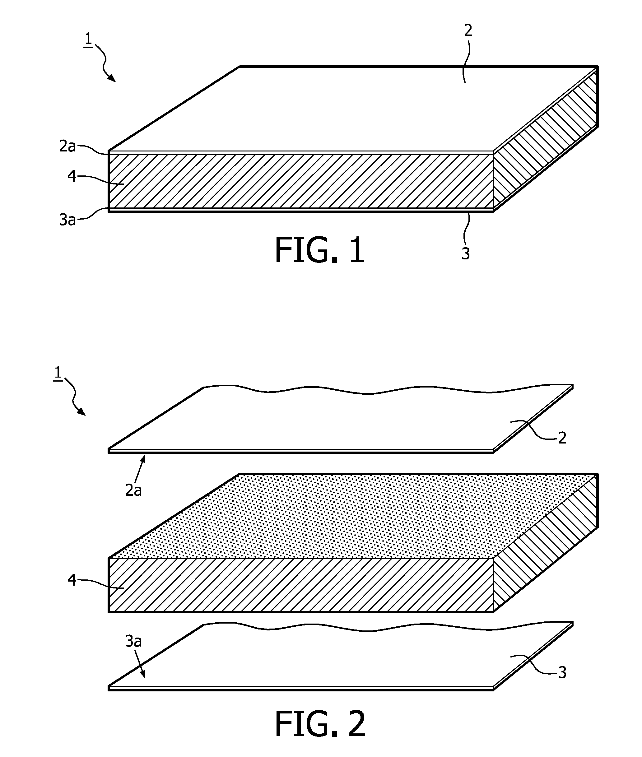
[0048]FIG. 1 shows a floor panel 1 according to the state of the art. The floor panel 1 is built up of a first skin layer 2, which corresponds to the top layer of the floor panel, and a second skin layer 3, which corresponds to the bottom layer. In between the top layer 2 and bottom layer 3 a core 4 is positioned. The core 4 is adhered to the inner surface 2a of the top layer 2 and to the inner surface 3a of bottom layer 3. The top layer 2, bottom layer 3 and core 4 have equal length and width. For clarity purposes, FIG. 2 shows an exploded view of the floor panel 1 of FIG. 1.

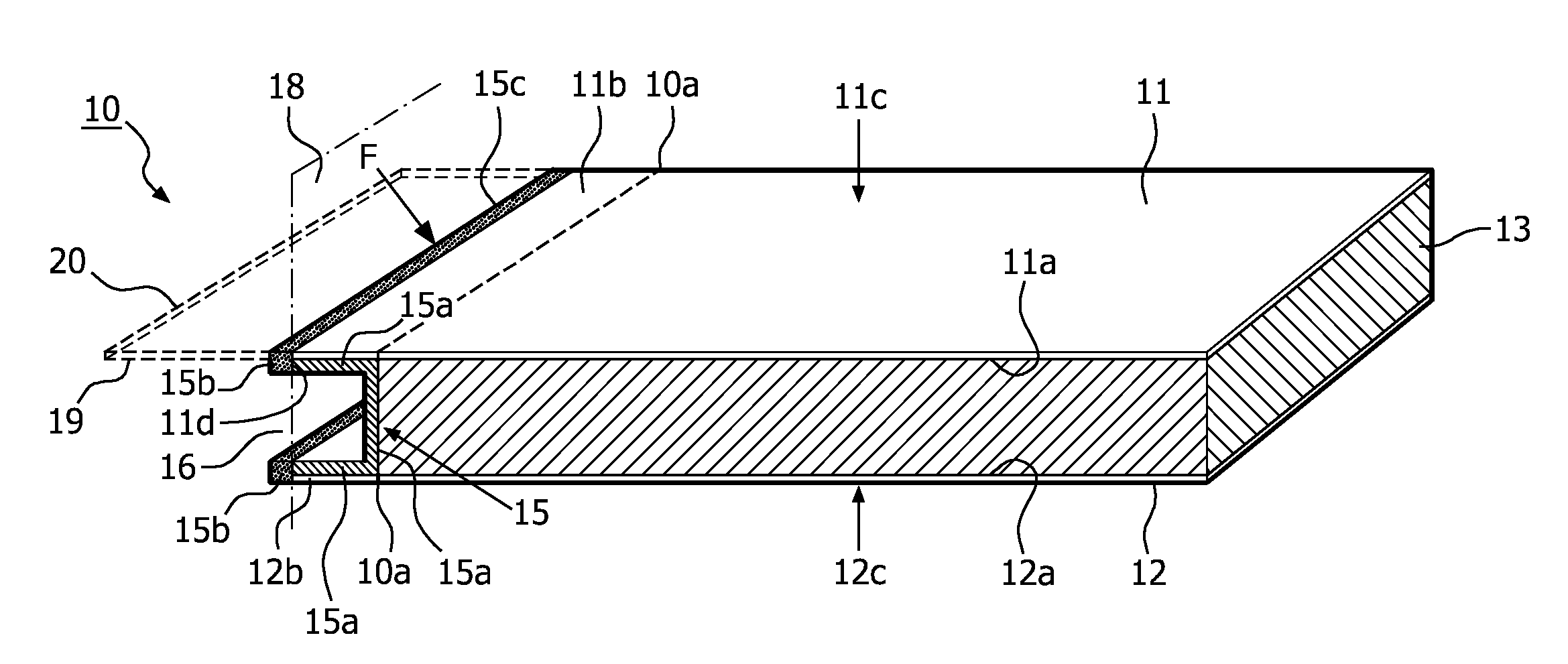
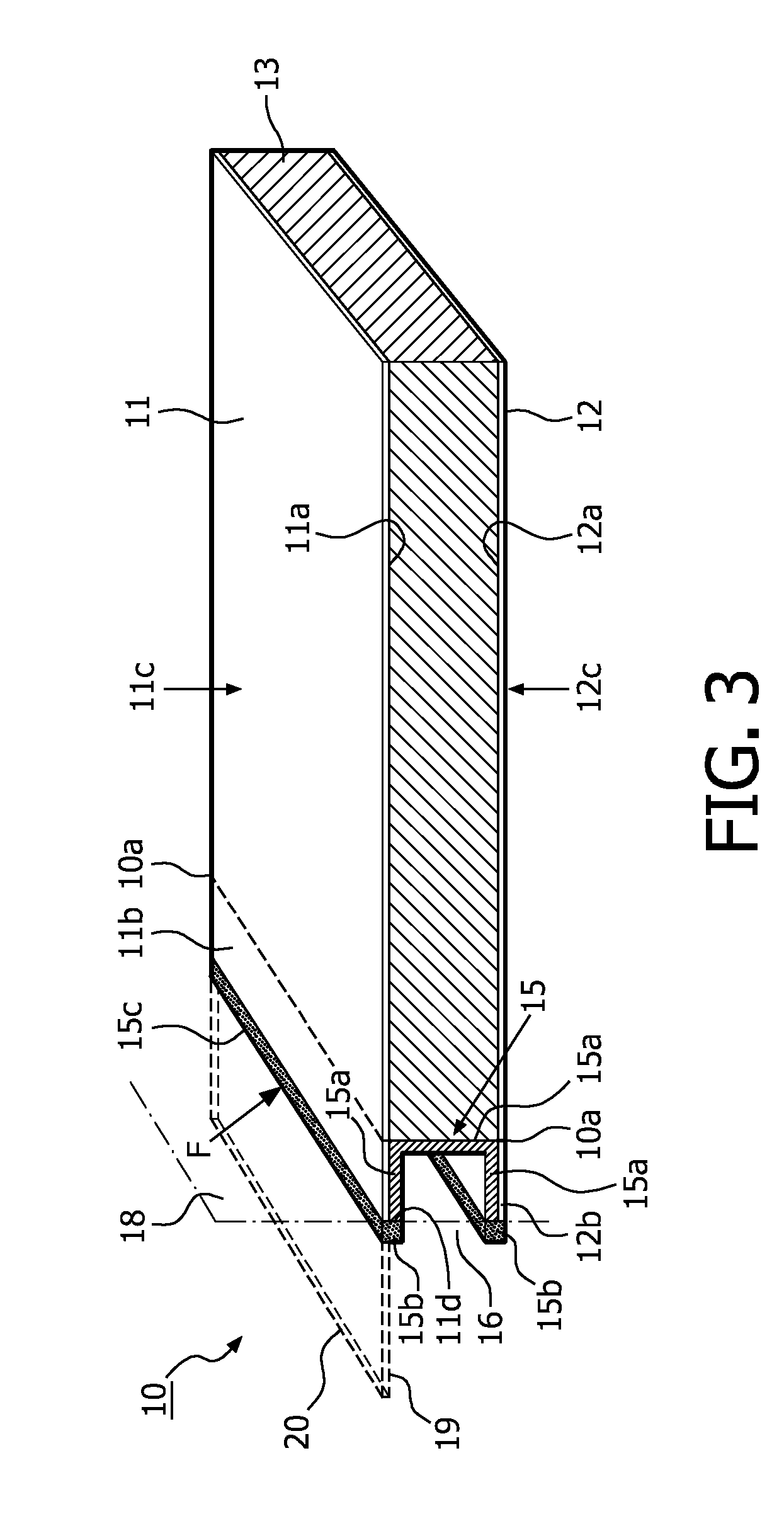
[0049]FIG. 3 shows a perspective view on a fl...


PUM

PropertyMeasurementUnit
Fractionaaaaaaaaaa
Fractionaaaaaaaaaa
Fractionaaaaaaaaaa

Abstract

The invention relates to a sandwich panel, comprising two skin layers and, connected thereto, a core layer in between. The first skin layer extends beyond the core at an edge of the panel by a protruding part, thereby defining an open edge space of the panel. The panel is further provided with a support member for the protruding part, the support member having a first part, extending inside the open edge space, and having a second part extending outside the open edge space and up to the plane, defined by the outer surface of the first skin layer. The panel provides an improved delamination resistance. The invention also relates to a support member for use in a sandwich panel according to the invention, and to a vehicle, in particular an aircraft, provided with the sandwich panel.

Description

FIELD OF THE INVENTION[0001]The present invention relates to a sandwich panel. The invention also relates to a support member for use in such a sandwich panel. The invention further relates to aircraft provided with such a sandwich panel, and to an assembly of two panels comprising the support member.BACKGROUND OF THE INVENTION[0002]Sandwich panels are used in a wide variety of applications, such as in vehicles or aircraft, and may be subject to extensive requirements regarding weight and strength. Sandwich panels combine stiffness and strength with low weight. Such sandwich panels are for instance described in US2007 / 0054087 A1, and comprise two skin layers and, connected thereto, a core layer in between. Typically an adhesive is used to connect the skin layers to the core. This connection may be critical, especially in case the core shows a low contact surface for connection to the skin layers, such as with a core made from honeycomb or (porous) foam. Loads, and in particular impa...

Claims


Application Information

Patent Timeline
IPC IPC(8): B32B3/00
CPCB32B3/08Y10T428/24331Y10T428/24752B32B5/08B32B5/18B32B7/12B32B15/08B32B15/20B32B27/065B32B27/12B32B27/38B32B3/02B32B3/12B32B2250/40B32B2260/021B32B2260/046B32B2262/0253B32B2262/0261B32B2262/101B32B2262/103B32B2262/106B32B2262/14B32B2307/3065B32B2605/00B32B2605/12B32B2605/18B32B2607/00
Inventor WERTHEN, JON MICHEALGUNNINK, JAN WILLEMEVANCHO, JOSEPH WILLIAM
Owner WERTHEN JON MICHEAL
Why Eureka
Try Eureka