Machinable composite material

a composite material and machine-machine technology, applied in the direction of synthetic resin layered products, vehicle components, climate sustainability, etc., can solve the problems of difficult to produce molded composite parts with tolerances, unable to re-mold molded composite parts to meet the changes in dimensions, and expensive mold making propositions

Active Publication Date: 2012-02-16
HEXCEL
View PDF9 Cites 36 Cited by
  • Summary
  • Abstract
  • Description
  • Claims
  • Application Information

AI Technical Summary

Benefits of technology

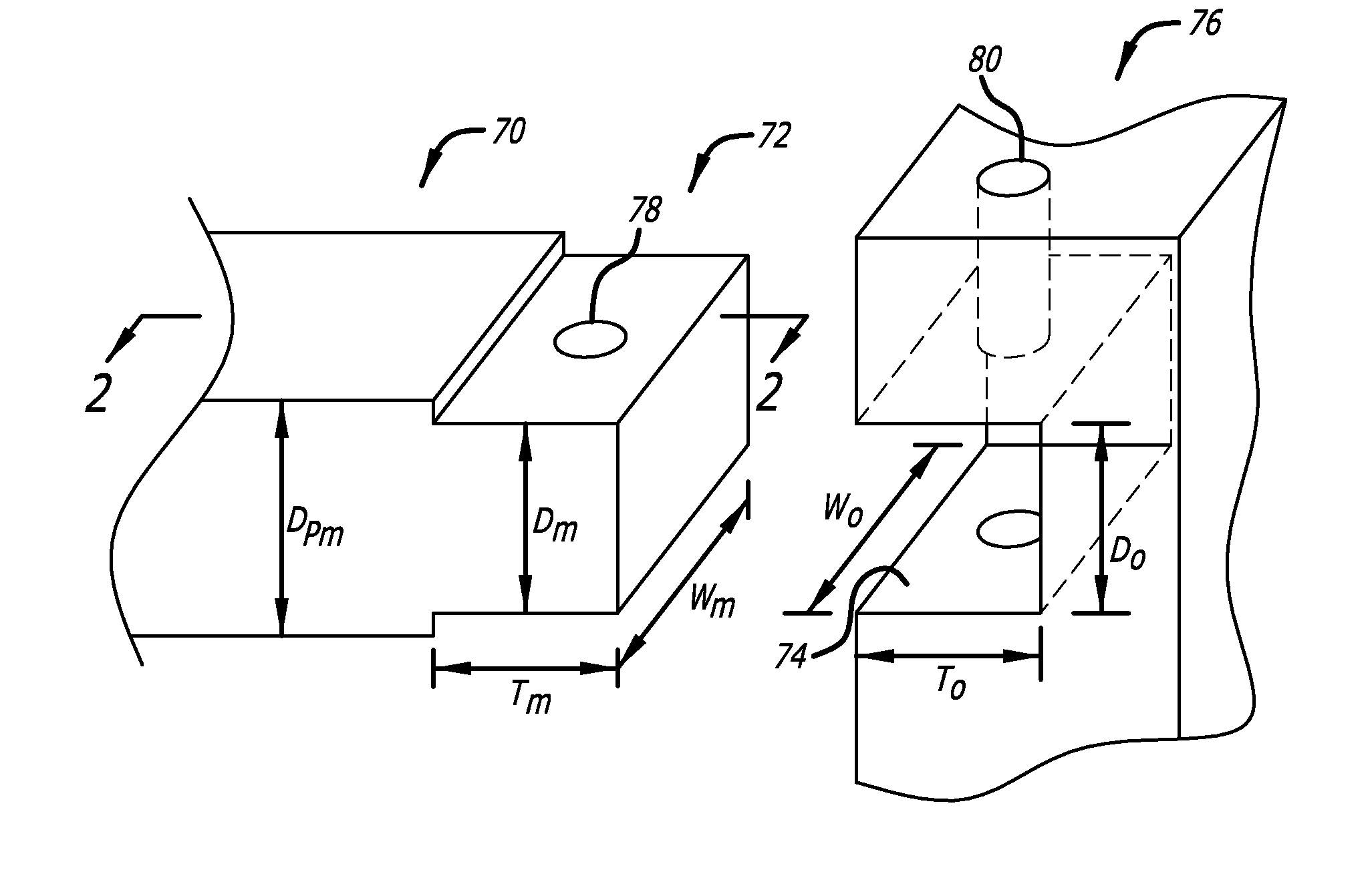
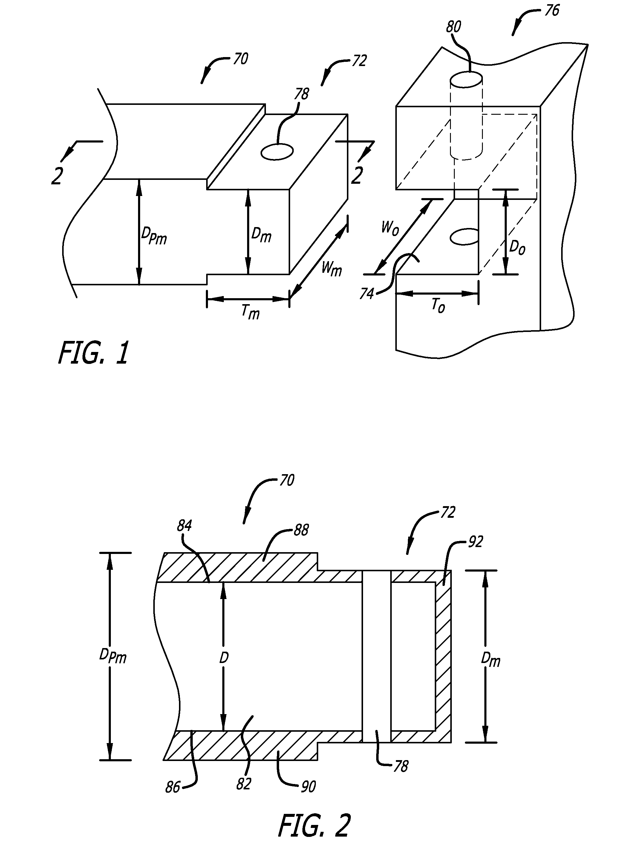
[0011]In accordance with the present invention, composite material is provided that can be machined in the same manner as metal to produce composite parts that have precise dimensions. The composite material can be machined as part of the initial fabrication process to provide composite parts having precise surface dimensions. The composite part can also be further machined to meet dimensional variations that may occur during the assembly process or which may be necessary due to belated design changes that may affect the dimensions of the part.

Problems solved by technology

It is an expensive proposition to make a different mold for each particular connector at a given location.
It is very difficult to produce molded composite parts that have tolerances which are as tight as the tolerances that can be obtained with a machined metal part.
In addition, a molded composite part cannot be remolded to meet the changes in dimensions that occur due to variables in the assembly process.
It is difficult to machine composite parts without creating structural damage.
The fibers tend to be disrupted and delamination can occur which greatly reduces the strength of the part.
Composite parts that contain UD fibers are particularly difficult to machine without adversely affecting the strength of the part.

Method used


Image

  • Machinable composite material
  • Machinable composite material
  • Machinable composite material

Examples


Embodiment Construction

[0033]The machinable composite materials in accordance with the present invention may be used for any intended purpose. However, they are preferably used in aerospace vehicles and particularly preferred for use in commercial and military aircrafts. For example, the machinable composite materials may be used to make non-primary (secondary) aircraft structures. However, the preferred use of the machinable composite material is for structural applications, such as connecting primary aircraft structures together. Primary aircraft structures or parts are those elements of either fixed-wing or rotary wing aircraft that undergo significant stress during flight and which are essential for the aircraft to maintain controlled flight. The machinable composite materials may also be used for other structural applications to make load-bearing parts and structures in general.

[0034]FIG. 5 depicts a fixed-wing aircraft at 10 that includes a number of exemplary primary aircraft structures and parts t...


PUM

PropertyMeasurementUnit
thicknessaaaaaaaaaa
thicknessaaaaaaaaaa
thicknessaaaaaaaaaa

Abstract

An assembly that includes a first part composed of a fibrous structure that includes fibers and a cured resin matrix. The fibrous structure has at least one surface and a layer that is located on the surface. The layer includes a discontinuous fiber composite that is composed of randomly oriented short fibers and a cured resin matrix wherein the layer has been machined to provide a machined surface. The assembly also includes a second part that is attached to the first part. The second part includes at least one surface that fits against the machined surface on the first part.

Description

[0001]This application is a divisional of U.S. patent application Ser. No. 12 / 856,210, which was filed on Aug. 13, 2010.BACKGROUND OF THE INVENTION[0002]1. Field of the Invention[0003]The present invention relates generally to molded composite materials. More particularly, the present invention is directed to molded composite materials that are suitable for structural applications and which can be machined accurately to provide precise fitting of parts together or other benefits.[0004]2. Description of Related Art[0005]Composite materials typically include fibers and a resin matrix as the two principal components. Composite materials typically have a rather high strength to weight ratio. As a result, composite materials are being used in demanding environments, such as in the field of aerospace where the high strength and relatively light weight of composite parts are of particular importance.[0006]Compression molding of thermosetting or thermoplastic composite materials is often us...

Claims


Application Information

Patent Timeline
Patent Type & Authority Applications(United States)
IPC IPC(8): B32B25/02
CPCB32B5/022B32B5/024B32B5/26B32B5/28B32B27/04B32B2605/18Y02T50/43C08J5/04C08J5/24B29C70/545B29C70/68Y02T50/433B64F5/0009B64F5/10B32B27/281B32B27/286B32B27/288B32B27/30B32B27/36B32B27/38B32B27/42B32B2262/0253B32B2262/0269B32B2262/101B32B2262/106B32B2307/72B32B2307/732Y10T428/24995Y10T428/249933Y10T428/249939Y10T428/249923Y10T428/249942Y02T50/40C08J5/243
Inventor BOURSIER, BRUNO
Owner HEXCEL
Why Eureka
Try Eureka