Supercharge Your Innovation With Domain-Expert AI Agents!

CMP slurry recycling system and methods

a technology of chemical mechanical polishing and slurry recycling, which is applied in the direction of other chemical processes, water/sewage treatment, multi-stage separation processes, etc., can solve the problems of slurry recycling being a complex process involving a number of processing steps, affecting the effect of material loss, and affecting the quality of slurry, etc., to achieve the effect of low shear

Inactive Publication Date: 2012-02-23
CABOT MICROELECTRONICS CORP
View PDF9 Cites 6 Cited by
  • Summary
  • Abstract
  • Description
  • Claims
  • Application Information

AI Technical Summary

Benefits of technology

[0013]In another aspect, the present invention also provides a chemical mechanical polishing (CMP) slurry recycling system, which comprises (a) a receiving tank adapted for collecting a waste stream from one or more polishing operations; (b) optionally, a pre-separation unit to remove coarse waste materials from the waste stream, (c) an in-line ultrafiltration unit, the ultrafiltration unit being adapted for removing water from CMP slurry being circulated through the unit; (d) a low shear in-line pump, such as a bearingless magnetic centrifugal pump, in fluid communication with the circulation line to propel the CMP slurry from the tank, through the circulation line and ultrafiltration unit, and back into the tank; and (e) optionally, a collection vessel to accumulate the concentrated slurry, (f) suitable means to adjust the pH and chemical composition of the slurry after concentration, (g) a means to introduce a portion of fresh, non-recycled slurry if desired, (h) optionally, analytical instrumentation to provide quality control on the output slurry and (i) a means to introduce the reconstituted slurry back to the polishing system.

Problems solved by technology

During the CMP process the CMP slurry typically becomes diluted and contaminated with debris, metal ions, oxides, and other chemicals, necessitating a continual application of slurry onto the pad and removal of slurry from the pad.
As noted above, the abrasive slurry generally becomes diluted and contaminated with materials derived from the article being polished as well as materials from the polishing pad, and decomposition products of CMP slurry components themselves.
Thus slurry recycling can be a complex process involving a number of processing steps and loss of materials due to inefficiencies in recycling techniques.

Method used


Image

  • CMP slurry recycling system and methods
  • CMP slurry recycling system and methods
  • CMP slurry recycling system and methods

Examples


example 1

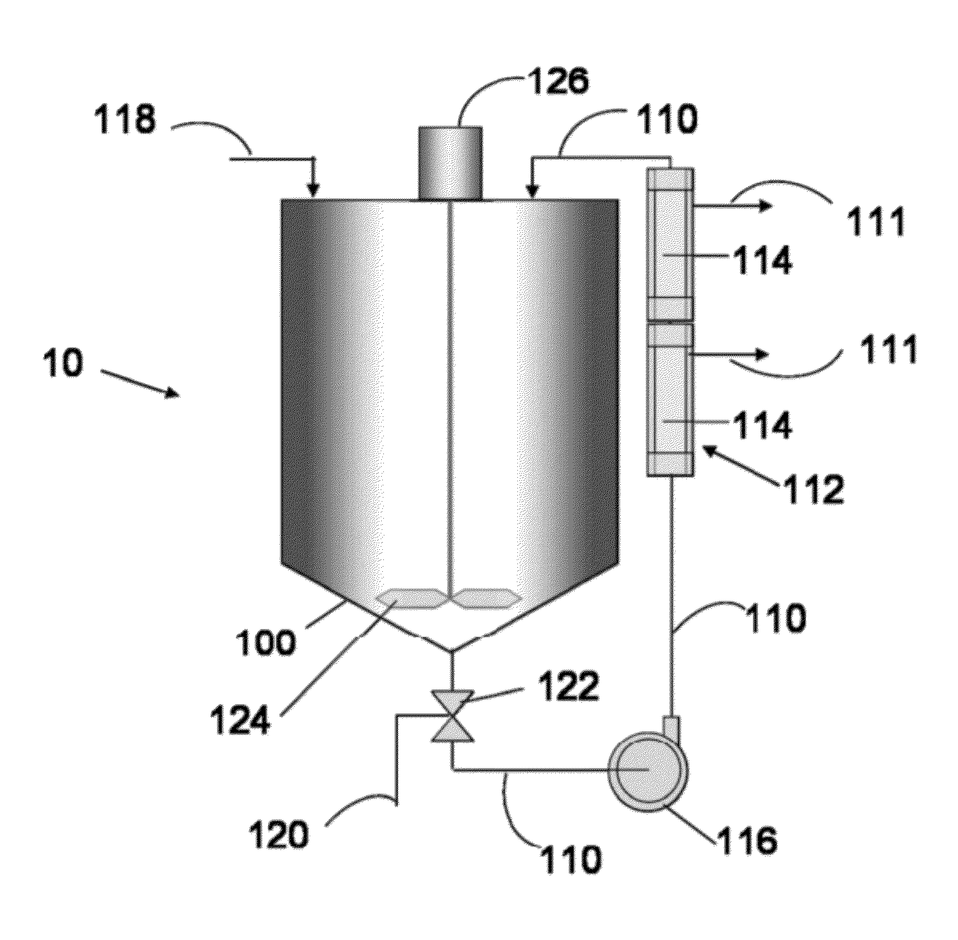
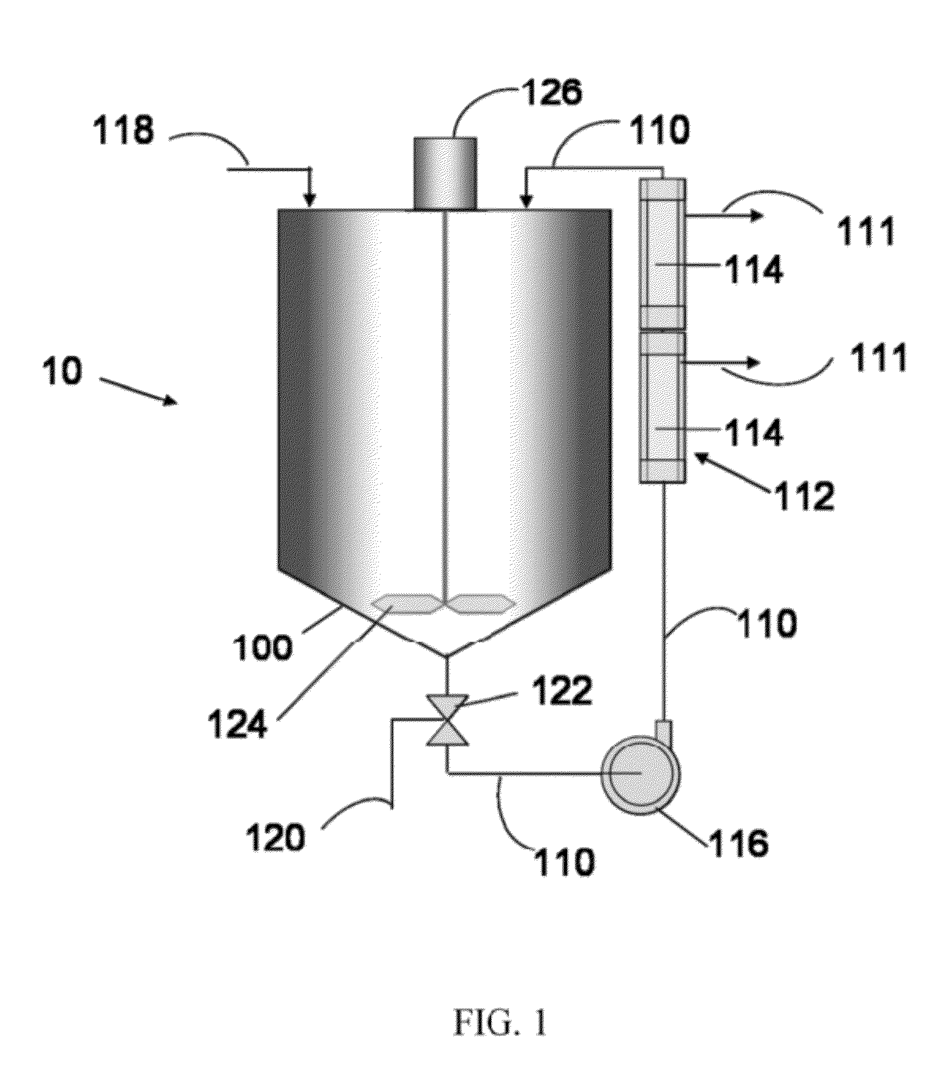
[0033]A recovered CMP slurry from a polishing operation is charged into a blending tank. The recovered slurry comprises a silica abrasive suspended in an aqueous carrier having a pH of about 9 to about 10, with an abrasive concentration of about 5 to about 10 percent by weight. The virgin, or fresh, non-recycle slurry (SS12, Cabot Microelectronics Corporation, Aurora, Ill.) from which the waste was generated has the following specifications: pH 10-11, silica concentration about 12.5 to about 12.6 percent by weight, a weight average silica particle size, Dw, of about 185 to 190 nm as determined using the CPS disk centrifuge. The recovered CMP slurry is pumped via a bearingless magnetic centrifugal pump from the tank though a circulation line into an ultrafiltration unit, and then back into the tank. The ultrafiltration unit is adapted to remove water from the recovered slurry passing through the unit. The recovered slurry is circulated through the ultrafiltration unit for a period of...

example 2

[0035]Following the general procedure outlined in Example 1, a silica based slurry recovered from a commercial polishing operation was recycled, without addition of fresh slurry. The recycled slurry was then used in a successive commercial polishing operation, and then again recycled. This process was repeated such that there were 7 polishing runs that used successively recovered and recycled slurry. The weight average particle size, Dw, and the number average particle size, Dn, were monitored in each of the original and recycle runs. FIG. 3 provides scatter plots of Dw (Panel A) and of particle polydispersity Dw / Dn (Panel B) for the seven successive recycling runs. Particle sizes described herein were determined using a CPS Instruments Incorporated disk centrifuge assuming an aggregate density of 1.33 g / cm3. As can be seen in FIG. 3, there is a gradual decrease in Dw as the number of recycles increases. Microscopic analysis of samples from the recycled slurries indicate the presenc...

example 3

[0036]Following the general procedure outlined in Example 1, a silica slurry recovered from a commercial polishing operation was repeatedly recycled, without addition of fresh slurry, as described in Example 2. The metal content of selected metals (e.g., Al, B, Ca, Co, Cr, Cu, Fe, K, Mg, Mn, Na, Ni, Ti, Zn, Zr) in the recycled slurries from the successive runs were monitored. The following trends were observed: Al, Ca, Cr. Cu, Fe, Mg, Mn, Ni, Ti, and Zn concentrations tended to increase, although not to levels above the specifications of the corresponding fresh non-recycled slurry. The concentration of B unexpectedly decreased, while the concentrations of Co, K, Na, and Zr appeared to be relatively unaffected by the recycling. It is believed that the increase in certain metals may come from the polished substrates and from the polishing pads utilized during the polishing operation. The results here show that the recycling process of the present invention does not lead to accumulatio...


PUM

PropertyMeasurementUnit
particle sizeaaaaaaaaaa
densityaaaaaaaaaa
particle sizeaaaaaaaaaa

Abstract

The present invention provides a system and method for recycling an abrasive chemical mechanical polishing (CMP) slurry after polishing substrates therewith. The method comprises circulating the recovered CMP slurry from a blending tank through an ultrafiltration unit and back into the, the ultrafiltration unit removing a predetermined amount of water from recovered slurry to form a slurry concentrate; optionally adjusting the pH of the concentrate to a predetermined target level; and optionally adding selected additive chemical components and / or water to the concentrate in amounts sufficient to form a reconstituted CMP slurry that is suitable for use in a CMP process.

Description

CROSS REFERENCE TO RELATED APPLICATIONS[0001]This application claims priority to provisional application No. 61 / 374,807 filed on Aug. 18, 2010.FIELD OF THE INVENTION[0002]This invention relates to chemical-mechanical polishing (CMP) compositions and methods. More particularly, this invention relates to methods for recycling CMP slurries and systems for performing such recycling, capture and reuse of abrasive particle.BACKGROUND OF THE INVENTION[0003]Compositions and methods for chemical-mechanical polishing of the surface of a substrate are well known in the art. Polishing compositions (also known as polishing slurries, CMP slurries, and CMP compositions) for CMP of surfaces of semiconductor substrates (e.g., integrated circuits) typically contain an abrasive, a fluid, various additive compounds, and the like.[0004]In general, CMP involves the concurrent chemical and mechanical abrasion of surface, e.g., abrasion of an overlying first layer to expose the surface of a non-planar seco...

Claims


Application Information

Patent Timeline
Patent Type & Authority Applications(United States)
IPC IPC(8): C09G1/02C09K13/00B01D61/14B01D15/04C09K3/14B01D36/00
CPCB01D61/145B01D2311/08B01D2311/12C09K3/1463B01D2315/14B01D2321/164C09G1/02B01D2311/18
Inventor AMOROSO, NICHOLASTOLLA, BRUNOBOLDRIDGE, DAVID
Owner CABOT MICROELECTRONICS CORP
Features
  • R&D
  • Intellectual Property
  • Life Sciences
  • Materials
  • Tech Scout
  • Unparalleled Data Quality
  • Higher Quality Content
  • 60% Fewer Hallucinations
Learn More