Oil dilution inhibiting apparatus and method

a technology of oil dilution and inhibiting apparatus, which is applied in the direction of engine starters, electric control, machines/engines, etc., can solve the problems of engine lowness, oil dilution by unburnt fuel likely more than expected, etc., and achieve the effect of increasing the oil temperatur

Inactive Publication Date: 2012-02-23
TOYOTA JIDOSHA KK
View PDF7 Cites 24 Cited by
  • Summary
  • Abstract
  • Description
  • Claims
  • Application Information

AI Technical Summary

Benefits of technology

[0050]According to this aspect, it is possible to increase the oil temperature by heating the engine oil. Moreover, for example, if the vehicle on which the oil diluti

Problems solved by technology

However, according to the aforementioned background art, for example, such a vehicle is not considered that is provided with an engine automatic stop/start apparatus (i.e. an economy run system or idling stop system) or the like and that the start and stop

Method used


Image

  • Oil dilution inhibiting apparatus and method
  • Oil dilution inhibiting apparatus and method
  • Oil dilution inhibiting apparatus and method

Examples


first embodiment

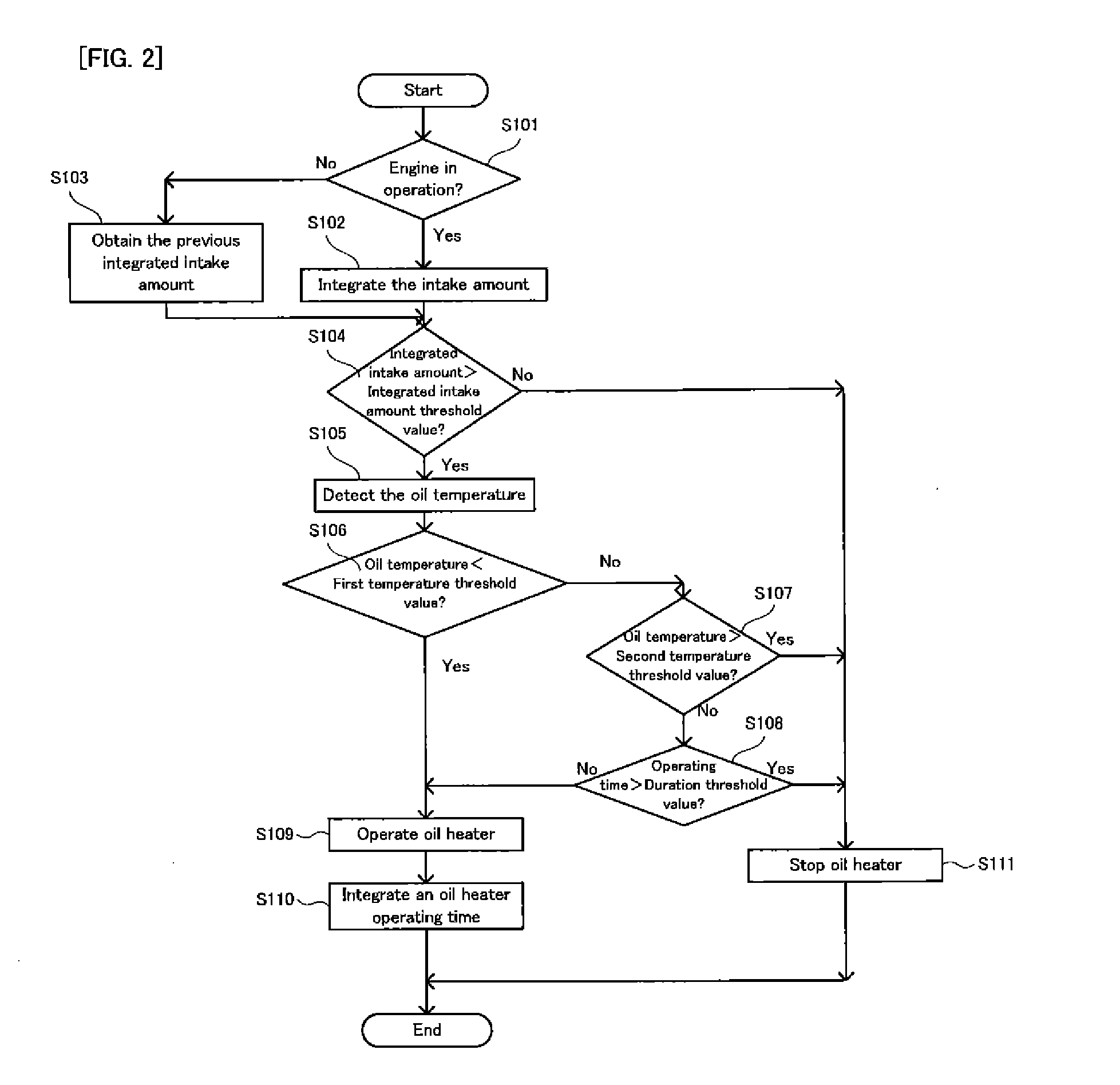
[0081]A first embodiment of the oil dilution inhibiting apparatus of the present invention will be explained with reference to FIG. 1 and FIG. 2.

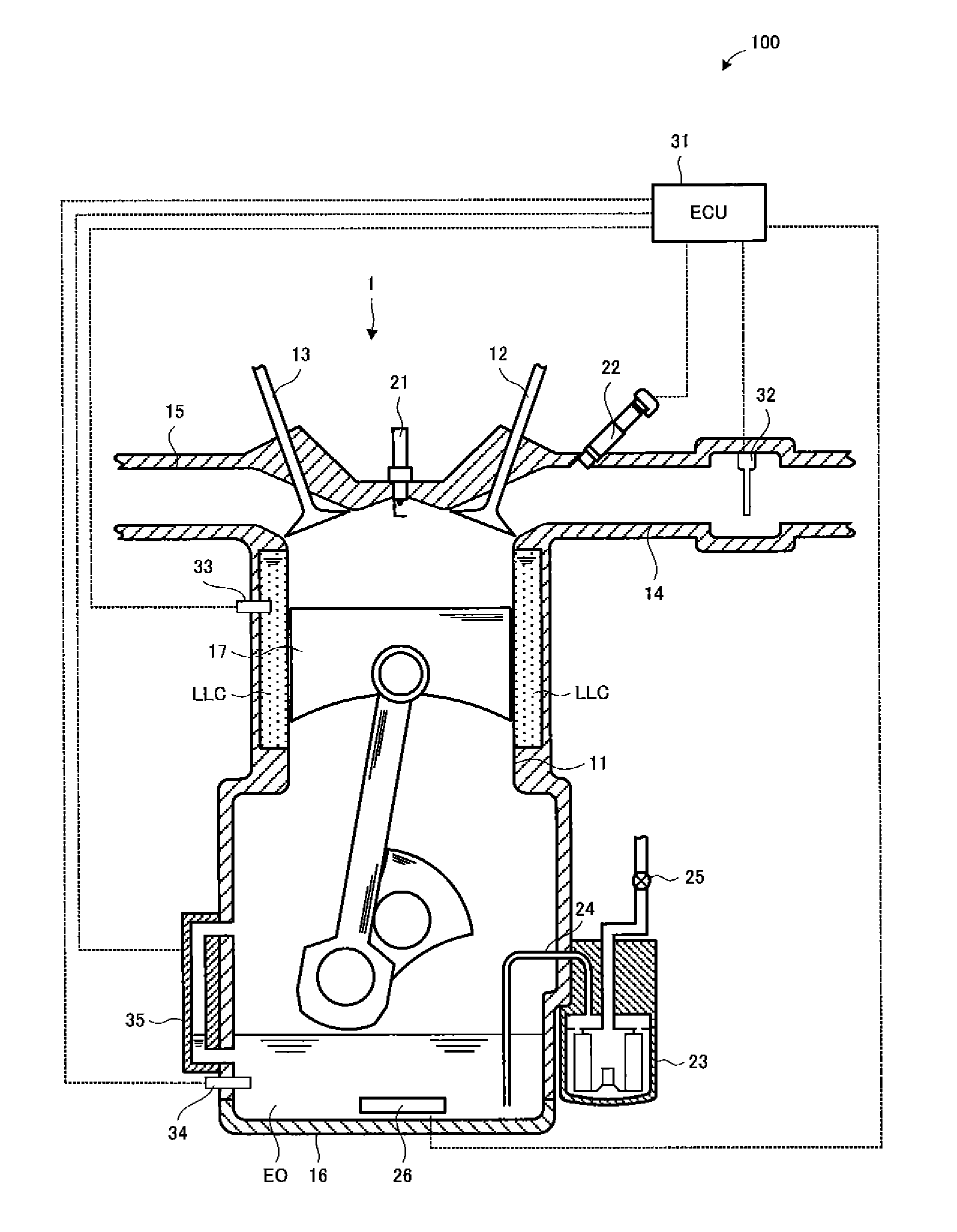
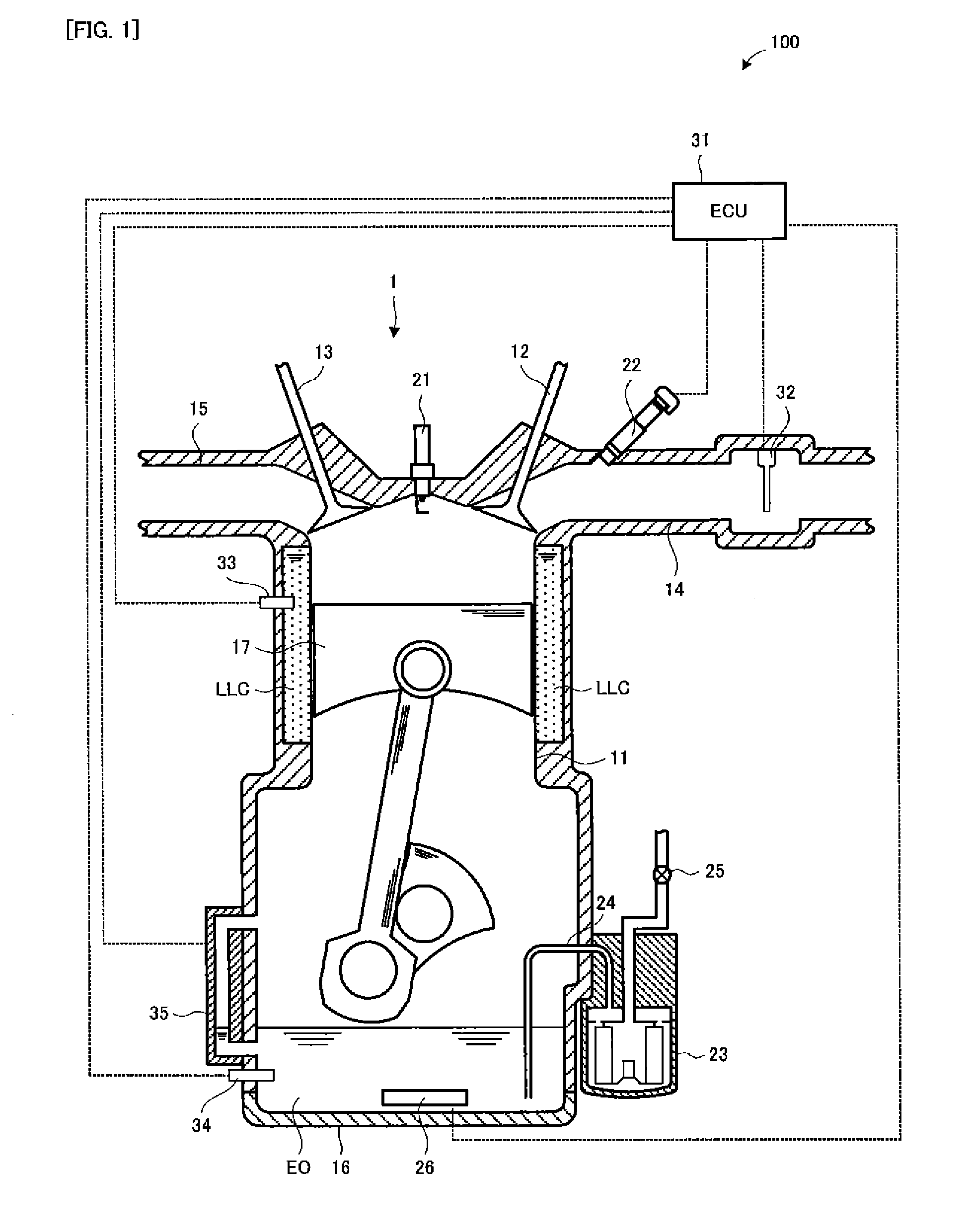
[0082]FIG. 1 is a block diagram showing the structure of an oil dilution inhibiting apparatus in the first embodiment.

[0083]In FIG. 1, an engine 1 provided for a vehicle (not illustrated) on which an oil dilution inhibiting apparatus 100 is mounted is provided with: a cylinder 11; an intake valve 12; an exhaust valve 13; an intake passage 14; an exhaust passage 15; an oil pan 16; a piston 17; an ignition plug 21; a fuel injection valve 22; an oil filter 23; and an oil heater 26.

[0084]Engine oil EO accumulated in the oil pan 16 flows into the oil filter 23 via an oil inflow passage 24. The engine oil EO which has passed through the oil filter 23 is pumped by the oil pump 25 and is supplied to a main gallery not illustrated. The fuel injection valve 22 is controlled by an ECU (Electronic Control Unit) 31 to inject alcohol fuel accumulated in ...

second embodiment

[0127]A second embodiment of the oil dilution inhibiting apparatus of the present invention will be explained with reference to FIG. 5. Except that the second embodiment has a different oil dilution inhibiting process performed by the ECU, the second embodiment has the same configuration as in the first embodiment. Thus, in the second embodiment, the overlap explanation with the first embodiment will be omitted. The common point will carry the same reference numeral in the drawing, and basically only a different point will be explained with reference to FIG. 5. FIG. 5 is a flowchart showing the oil dilution inhibiting process performed by the ECU in the second embodiment, to the same effect as in FIG. 2.

(If Oil Heater is OFF)

[0128]In FIG. 5, if the oil heater 26 is OFF (i.e. if it is not in the oil heating mode), firstly, the ECU 31 detects the state of the vehicle (step S301). Specifically, for example, the ECU 31 detects a vehicle speed, vehicle inclination, the number of revoluti...

third embodiment

[0148]A third embodiment of the oil dilution inhibiting apparatus of the present invention will be explained with reference to FIG. 6. Except that the third embodiment has a different oil dilution inhibiting process performed by the ECU, the third embodiment has the same configuration as in the first embodiment. Thus, in the third embodiment, the overlap explanation with the first embodiment will be omitted. The common point will carry the same reference numeral in the drawing, and basically only a different point will be explained with reference to FIG. 6. FIG. 6 is a flowchart showing the oil dilution inhibiting process performed by the ECU in the third embodiment, to the same effect as in FIG. 2.

(If Oil Heater is OFF)

[0149]In FIG. 6, if the oil heater 26 is OFF (i.e. if it is not in the oil heating mode), firstly, the ECU 31 obtains the oil temperature of the engine oil EO via the oil temperature sensor 34 (step S401). Then, the ECU 31 judges whether or not the obtained oil tempe...


PUM


Abstract

An oil dilution inhibiting apparatus is mounted on a vehicle provided with an engine in which alcohol fuel can be used, the oil dilution inhibiting apparatus provided with: an intake amount integrating device for integrating amount of an air sucked into the engine while the engine is in operation, thereby calculating an integrated intake amount; a temperature detecting device for detecting oil temperature of engine oil of the engine; and a controlling device for controlling the vehicle to move into an oil heating mode in which the oil temperature is increased in such conditions that the calculated integrated intake amount is greater than an integrated intake amount threshold value and that the detected oil temperature is less than a first temperature threshold value.

Description

TECHNICAL FIELD[0001]The present invention relates to an oil dilution inhibiting apparatus and method for inhibiting the dilution of engine oil by alcohol fuel, in a vehicle provided with an engine in which the alcohol fuel can be used.BACKGROUND ART[0002]If fuel is mixed into engine oil and thus the engine oil is diluted, for example, the lubricating ability of the engine oil is reduced.[0003]As this type of apparatus, for example, there has been suggested an internal combustion engine for increasing the temperature of lubricating oil by operating an oil heater if sub injection such as pilot injection and post injection is performed in tandem with main injection (refer to a patent document 1). Alternatively, there has been suggested an apparatus for setting the injection timing of the fuel in accordance with the counter value of a dilution counter associated with the oil dilution at the start of a diesel engine (refer to a patent document 2). Alternatively, there has been suggested...

Claims


Application Information

Patent Timeline
IPC IPC(8): F01M5/00
CPCF01M1/10F01M5/001F01M2001/165F02D41/0025F02N19/04F02D41/18F02D2200/023F02D2250/11F02N11/0814F02D41/068
Inventor KANAI, HIROSHI
Owner TOYOTA JIDOSHA KK
Why Eureka
Try Eureka