
Device housing a battery and charging apparatus for contactless charging

a charging apparatus and battery technology, applied in the direction of charging stations, electric vehicle charging technology, transportation and packaging, etc., can solve the problems of inability to charge the battery normally, the internal battery cannot be charged under optimal conditions, and the charging with the charging adapter may not always be possible, so as to achieve reliable detection of charging, simple circuit structure, and reliable determination

Inactive Publication Date: 2012-02-23
SANYO ELECTRIC CO LTD
View PDF14 Cites 84 Cited by
  • Summary
  • Abstract
  • Description
  • Claims
  • Application Information

AI Technical Summary

Benefits of technology

[0014]In the device housing a battery and charging apparatus of the present invention, when the device housing a battery 50, 150 is placed on the charging apparatus 10, 110 and the charging adapter 80, 180 is connected, the charging selection section 63 can charge the internal battery 52, 152 with only the charging adapter 80, 180 output. This device housing a battery has the characteristic that when it is placed on the contactless charging apparatus with the charging adapter connected, the internal battery can be rapidly charged under favorable conditions while limiting heat generation.
[0015]In the device housing a battery and charging apparatus of the present invention, the device housing a battery 50, 150 can be provided with a charging apparatus detection section 61 equipped with a microcomputer 64 that is operated by power output from the contactless charging section 60 to control contactless charging of the internal battery 52, 152. With the microcomputer 64 in the operating state due to power supplied from the charging apparatus 10, 110, the charging status of the charging apparatus 10, 110 can be detected by the charging apparatus detection section 61. In this device housing a battery, the microcomputer, which is provided in the charging apparatus detection section to control internal battery charging, is not operated by the internal battery. Specifically, the charging status of the charging apparatus can be detected with a simple circuit structure while reducing unnecessary internal battery power consumption. This is because the microcomputer is operated by power supplied via magnetic coupling with the charging apparatus to detect the charging status of the charging apparatus.
[0018]In the device housing a battery and charging apparatus of the present invention, the adapter detection section 62 can be provided with a first charging current detection circuit 68 that detects internal battery 52, 152 charging current, and a second charging current detection circuit 69 that detects charging current output from the charging apparatus 10, 110. Further, the adapter detection section 62 can detect charging by the charging adapter 80, 180 from the difference between the charging current detected by the first charging current detection circuit 68 and the second charging current detection circuit 69. This device housing a battery can reliably determine if the charging adapter is connected by the current difference between the first charging current detection circuit and the second charging current detection circuit.
[0019]The device housing a battery and charging apparatus of the present invention can be provided with a diode 75 between the charging adapter 80, 180 and the internal battery 52, 152, and the adapter detection section 62 can detect the adapter-side diode 75 voltage to detect charging by the charging adapter 80, 180. This device housing a battery can reliably detect charging from the charging adapter with a simple circuit structure.
[0020]In the device housing a battery and charging apparatus of the present invention, the adapter detection section 62 can detect charging adapter 80, 180 connection or charging, and send a signal to the charging apparatus 10, 110 to halt charging, or stop internal battery 52, 152 charging by the contactless charging section 60. In this device housing a battery, since power transmission from the charging apparatus can be stopped when the charging adapter is connected and charging the internal battery, unnecessary power consumption can be reduced and the internal battery can be efficiently charged. Further, when not charging the internal battery, charging apparatus power transmission can be stopped to prevent heat generation due to magnetic induction in the device housing a battery and the internal battery.
[0021]In the device housing a battery and charging apparatus of the present invention, the adapter detection section 62 (equivalent to an external power source detection section 242) is provided with an adapter detection circuit 242C activated by voltage applied by connecting the charging adapter 80 (equivalent to an external power source 220), and the adapter detection circuit 242C issues a connection signal to the adapter detection section 62 to detect charging adapter 80 connection. This device housing a battery can detect charging adapter 80 connection with a simple structure.

Problems solved by technology

Consequently, if the internal battery is charged by both the contactless charging pad and the charging adapter, the battery cannot be charged normally.
If the charging adapter is connected to the device housing a battery when it is, being charged by the contactless charging pad, the charging circuit that charges the internal battery from the charging adapter does not perform charging.
However, since charging by the charging adapter is halted when contactless charging pad battery charging current is detected, rapid charging of the internal battery under optimal conditions may not always be possible.
For example, the system has the drawback that even under conditions where the internal battery can be rapidly charged by the charging adapter, charging with the charging adapter may not be possible.

Method used


Image

  • Device housing a battery and charging apparatus for contactless charging
  • Device housing a battery and charging apparatus for contactless charging
  • Device housing a battery and charging apparatus for contactless charging

Examples


Embodiment Construction

)

[0039]The following describes embodiments of the present invention based on the figures. However, the following embodiments are merely specific examples of a device housing a battery and charging apparatus representative of the technology associated with the present invention, and the device housing a battery and charging apparatus of the present invention are not limited to the embodiments described below. Further, components indicated in the appended claims are in no way limited to the components indicated in the embodiments.

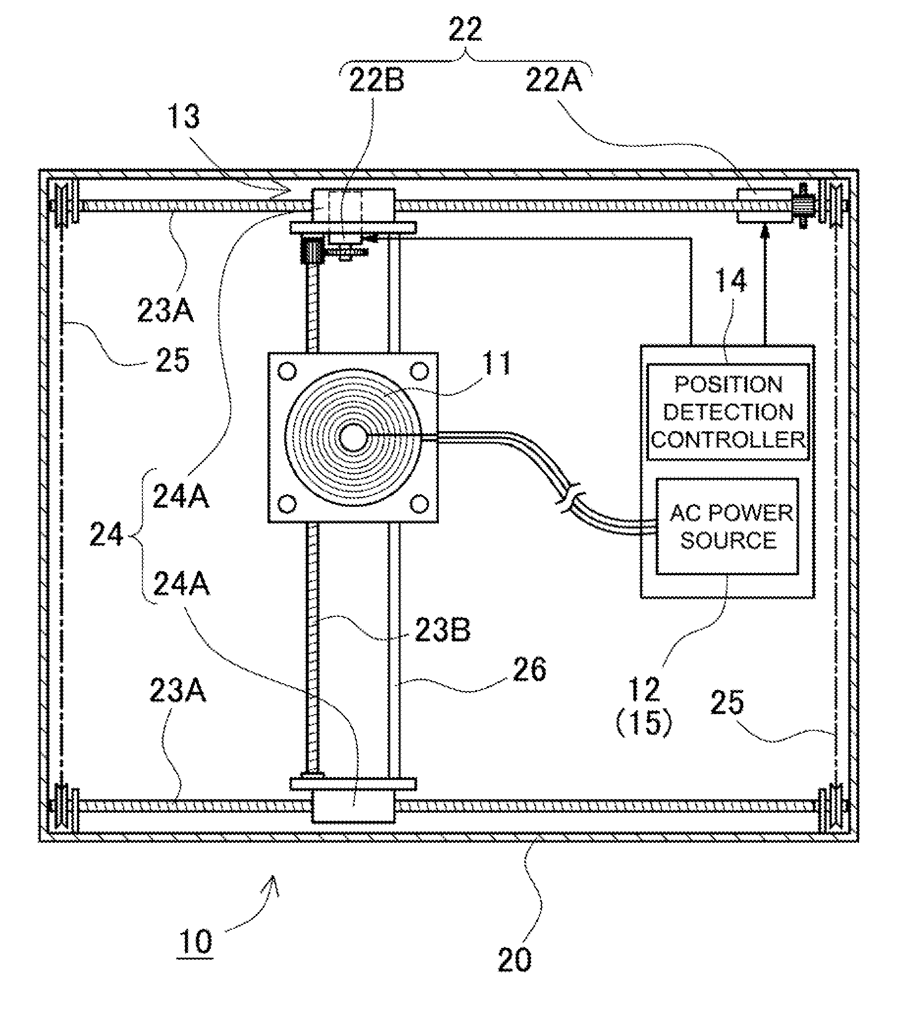
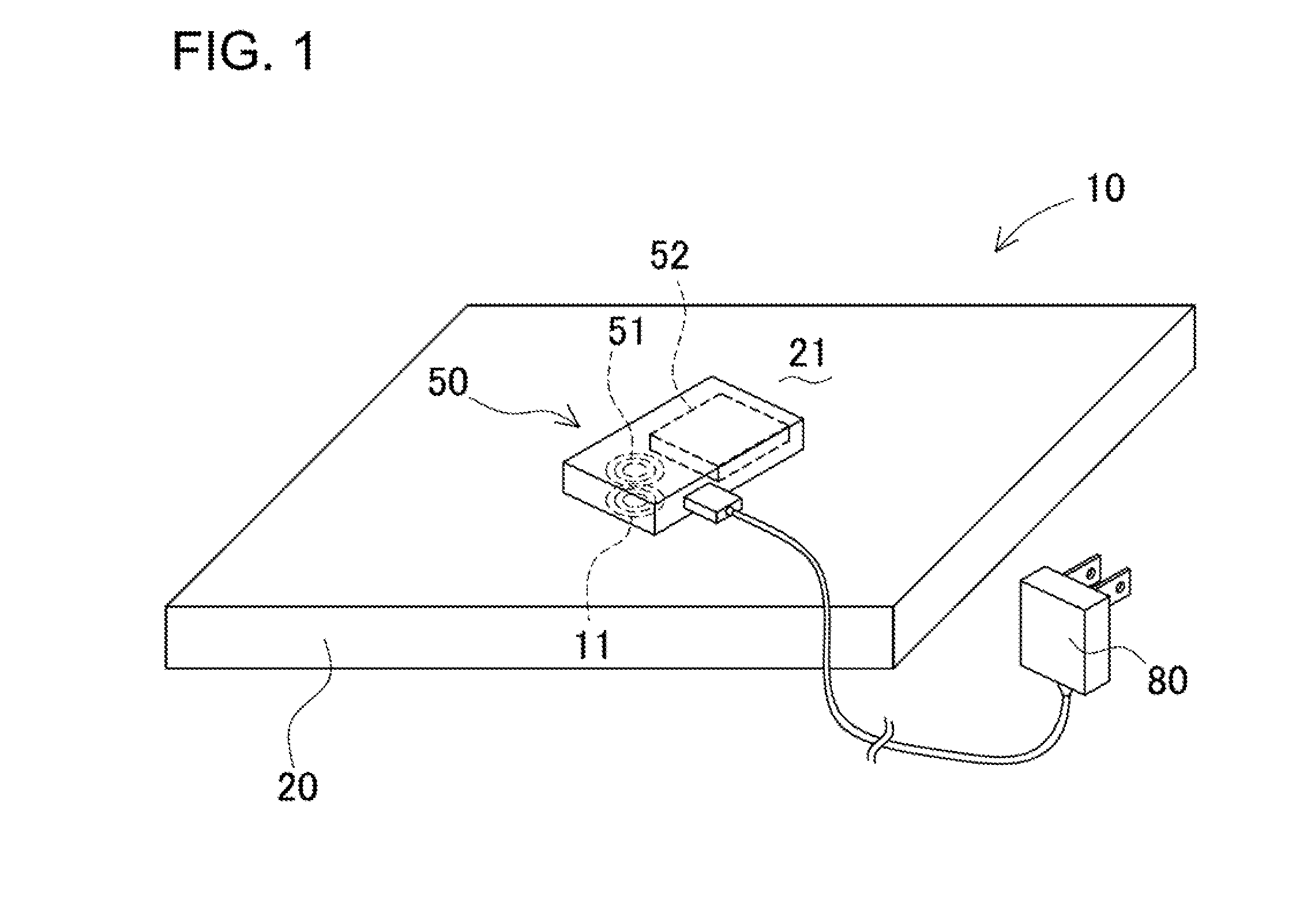
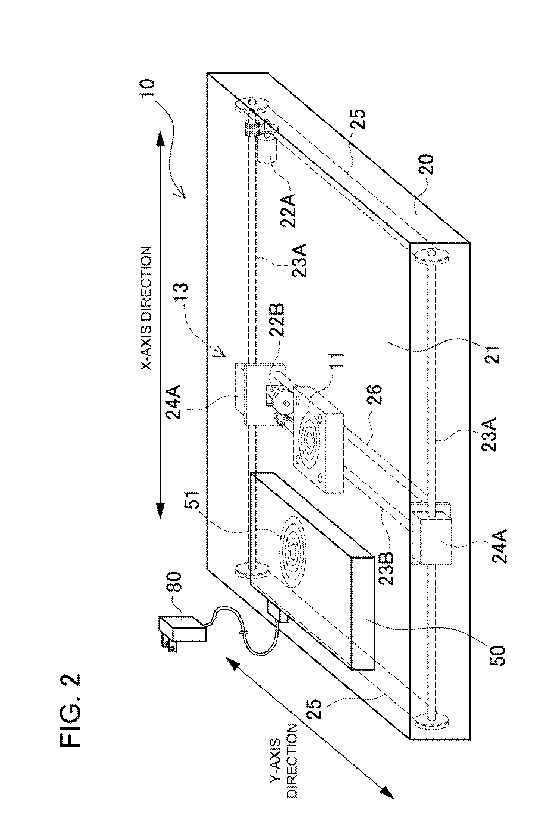
[0040]FIGS. 1-7 show structural overviews and diagrams illustrating the operating principles of the charging apparatus 10. As shown in FIGS. 1, 2, and 7, a device housing a battery 50 is placed on top of the charging apparatus 10 and power is transmitted by magnetic induction to charge the internal battery 52. The device housing a battery 50 is provided with an internal battery 52, charging terminals 72 that connect with a charging adapter 80 that charges the...


PUM


Abstract

A device housing a battery 50 has charging terminals 72 for connection of a charging adapter 80 and a contactless charging section 60. A charging apparatus 10 performs contactless charging of the device housing a battery 50 placed on the charging apparatus 10. The device housing a battery 50 is provided with a charging apparatus detection section 61 that detects placement on the charging apparatus 10, an adapter detection section 62 that detects charging adapter 80 connection or charging, and a charging selection section 63 that selects internal battery 52 charging by either the charging apparatus 10 or the charging adapter 80. When the device housing a battery 50 is placed on the charging apparatus 10 and the charging adapter 80 is connected, the charging selection section 63 controls either the charging apparatus 10 or the charging adapter 80 to charge the internal battery 52.

Description

BACKGROUND OF THE INVENTION[0001]1. Field of the Invention[0002]The present invention relates to a device housing a battery (batteries) such as a battery pack or mobile telephone, and to a charging apparatus that transmits power by magnetic induction to the device housing a battery to charge the battery inside.[0003]2. Description of the Related Art[0004]A contactless charging pad (charging stand, charging cradle) has been developed to charge a battery inside a device housing a battery such as a battery pack or a notebook computer. Battery charging is performed by transmitting power from a power supply coil (transmitting coil, primary coil) to an induction coil (receiving coil, secondary coil) by magnetic induction (refer to Japanese Laid-Open Patent Publication 2005-110409).[0005]JP 2005-110409-A cites a configuration with a contactless charging pad that houses a power supply coil driven by an alternating current (AC) power source, and a device housing a battery such as a battery p...

Claims


Application Information

Patent Timeline
IPC IPC(8): H02J7/04H02J7/00
CPCH02J7/025Y02T90/122B60L11/182B60L11/1829B60L11/1833H02J5/005Y02T90/121Y02T10/7005Y02T90/125Y02T10/7011Y02T90/14B60L11/1816H02J7/0052Y02T10/7072B60L53/14B60L53/38B60L53/36B60L53/124B60L53/126Y02T10/70Y02T90/12H02J50/005H02J50/80H02J50/90H02J50/12H02J50/60H02J7/00034H02J7/02H02J7/00
Inventor TERAO, KYOZOITAGAKI, SHINICHIMINAMI, SADAO
Owner SANYO ELECTRIC CO LTD
Learn More