
Fiber sampler for recovery of bioaerosols and particles

a bioaerosol and particle technology, applied in biomass after-treatment, instruments, apparatus sterilization, etc., can solve the problems of organisms dying during collection, current sampling methods on microbiological media do not permit extended sampling times beyond, and achieve the effect of maintaining the viability of the bioparticles collected

Inactive Publication Date: 2012-02-23
RES TRIANGLE INST
View PDF4 Cites 23 Cited by
  • Summary
  • Abstract
  • Description
  • Claims
  • Application Information

AI Technical Summary

Problems solved by technology

In addition to the problem of collecting the aerosol (particles) is the problem of recovering the particles for analysis.
In the case of biological particles, a common problem is that the organisms die during collection or after collection while awaiting laboratory analysis.
Current sampling methods onto microbiological media do not permit extended sampling times beyond 30-45 minutes in the case where preservation of viable organisms is of interest.
Each bioaerosol sampling method has limitations with respect to sampling time, desiccation, shelf life of sample, complexity, compatibility with analysis via PCR and live recovery.
Impactors are limited with respect to sampling time because the collection media used to enumerate the number of colonies of organisms for viability after collection is subject to desiccation, thus limiting the sampling time.
Impingers are limited in their sampling time from the evaporation of the collecting fluid.
An example consequence is that in portable samplers operation is severely limited due to battery life in the samplers with filters with high pressure drop.
Further, the flow of air through the filters or membranes after a biological aerosol has been trapped can lead to the desiccation of the medium about the bioaerosol and death of the bioaerosol.

Method used


Image

  • Fiber sampler for recovery of bioaerosols and particles
  • Fiber sampler for recovery of bioaerosols and particles
  • Fiber sampler for recovery of bioaerosols and particles

Examples


Embodiment Construction

[0062]As used herein, “bioparticles” means microbes and other biological particles such as for example bacteria, viruses, and biologically derived particles such as proteins, cell fragments, etc.

[0063]As used herein, “viable” or “viability” is defined as the capability of having a collected organism becoming active again after being placed into a favorable environment. For example, a collected bacteria spore or vegetative bacterium being placed into a growth media and incubated under appropriate conditions for growth resulting in growth and reproduction of the organism. For example, a collected virus being exposed to its desired host and incubated under appropriate conditions resulting in the virus infecting the host.

[0064]As used herein, “collection viability” means the capability to keep a percentage of bioparticles in a collection medium of this invention alive during the collection event.

[0065]As used herein, “storage viability” means the capability to keep a percentage of biopa...


PUM

PropertyMeasurementUnit
diameteraaaaaaaaaa
thicknessaaaaaaaaaa
thicknessaaaaaaaaaa

Abstract

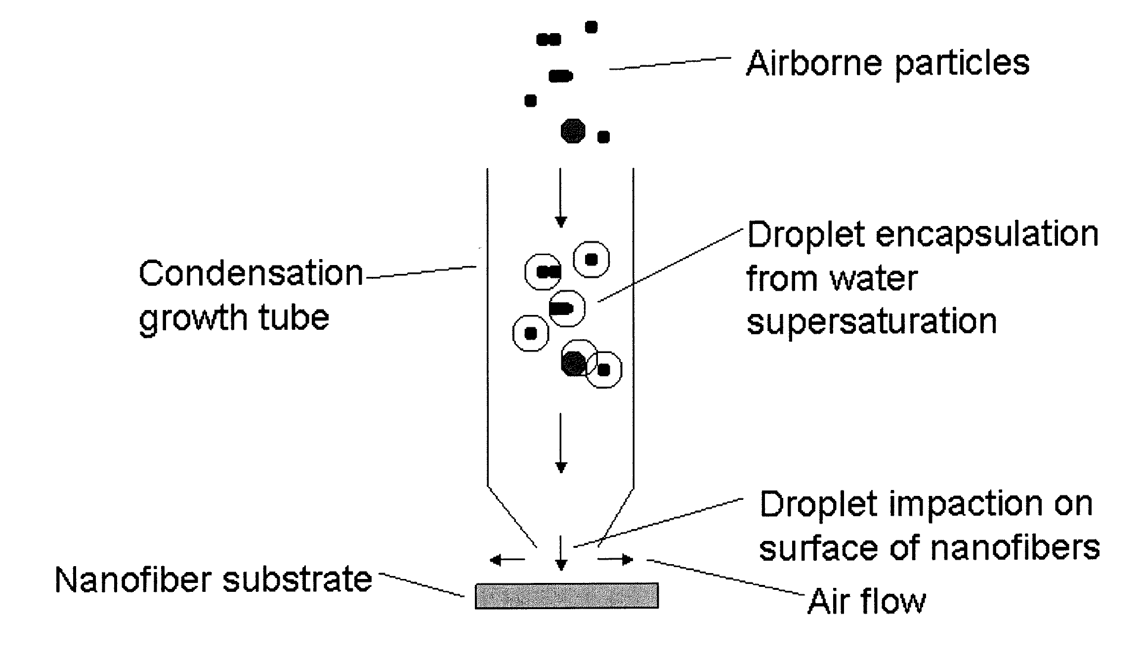
A bioparticle collection device and an aerosol collection system. The bioparticle collection device includes a collection medium including a plurality of fibers formed into a fiber mat and configured to collect bioparticles thereon, and includes a viability enhancing material provider disposed in a vicinity of the plurality of fibers and configured to provide a viability enhancing material to the collected bioparticles to maintain viability of the bioparticles collected by the fiber mat. The aerosol collection system includes an aerosol pumping device configured to entrain particles in an gas stream, an aerosol saturation device configured to saturate the particles in the gas stream with a biocompatible liquid, and an aerosol collection medium downstream from the aerosol saturation device and including a plurality of fibers formed into a fiber mat for collection of the saturated aerosol particles.

Description

CROSS REFERENCE TO RELATED APPLICATIONS[0001]This application is related to and claims priority under 35 U.S.C. 119(e) to U.S. Application Ser. No. 61 / 374,466, filed Aug. 17, 2010, entitled “Fiber Sampler for Recovery of Bioaerosols and Particles,” the entire contents of which are incorporated herein by reference.[0002]This application is related to U.S. application Ser. No. 11 / 559,282, filed on Nov. 13, 2006, entitled “Particle Filter System Incorporating Nanofibers,” the entire contents of which are incorporated herein by reference. This application is related to U.S. application Ser. No. 10 / 819,916, filed on Apr. 8, 2004, entitled “Electrospinning of Polymer Nanofibers Using a Rotating Spray Head,” the entire contents of which are incorporated herein by reference. This application is also related to U.S. application Ser. No. 10 / 819,942, filed on Apr. 8, 2004, entitled “Electrospray / electrospinning Apparatus and Method,” the entire contents of which are incorporated herein by refe...

Claims


Application Information

Patent Timeline
Patent Type & Authority Applications(United States)
IPC IPC(8): C12Q1/70C12Q1/04C12M1/12B82Y15/00
CPCB82Y15/00G01N2001/2223G01N1/2214G01N1/2205G01N1/2208G01N33/497B01D2239/025B01D2239/0604C12Q1/24
Inventor ENSOR, DAVID S.WALLS, HOWARD J.FOARDE, KARIN K.
Owner RES TRIANGLE INST
Learn More