Downhole closed-loop geosteering methodology

a geosteering and closed-loop technology, applied in the direction of surveying, directional drilling, borehole/well accessories, etc., can solve the problems of increasing the difficulty of drilling, so as to improve the timeliness and accuracy of geosteering operations, reduce the tortuosity of the borehole, and improve the accuracy of drilling operations

Active Publication Date: 2012-02-23
SCHLUMBERGER TECH CORP
View PDF8 Cites 55 Cited by
  • Summary
  • Abstract
  • Description
  • Claims
  • Application Information

AI Technical Summary

Benefits of technology

[0007]Exemplary embodiments of the present invention may advantageously provide several technical advantages. For example, in providing a closed-loop methodology, the present invention tends to advantageously improve the timeliness and accuracy of geosteering operations. The invention tends to further improve borehole placement in the subterranean geology (e.g., in a predetermined payzone) while also reducing borehole tortuosity.

Problems solved by technology

For example, the viability of prior art geosteering methods is often limited by the bandwidth and accuracy of the communication channel between the bottom hole assembly (BHA) and the surface.
This limitation can cause geosteering methods to be slow and somewhat unresponsive (e.g., due to the time lag associated with transmitting LWD measurements to the surface and then transmitting steering instructions or a corrected well plan from the surface to the BHA).
Moreover, telemetry errors and / or the reduced accuracy that results from data compression can lead to further errors when computing the corrected well path.

Method used


Image

  • Downhole closed-loop geosteering methodology
  • Downhole closed-loop geosteering methodology
  • Downhole closed-loop geosteering methodology

Examples


embodiment 200

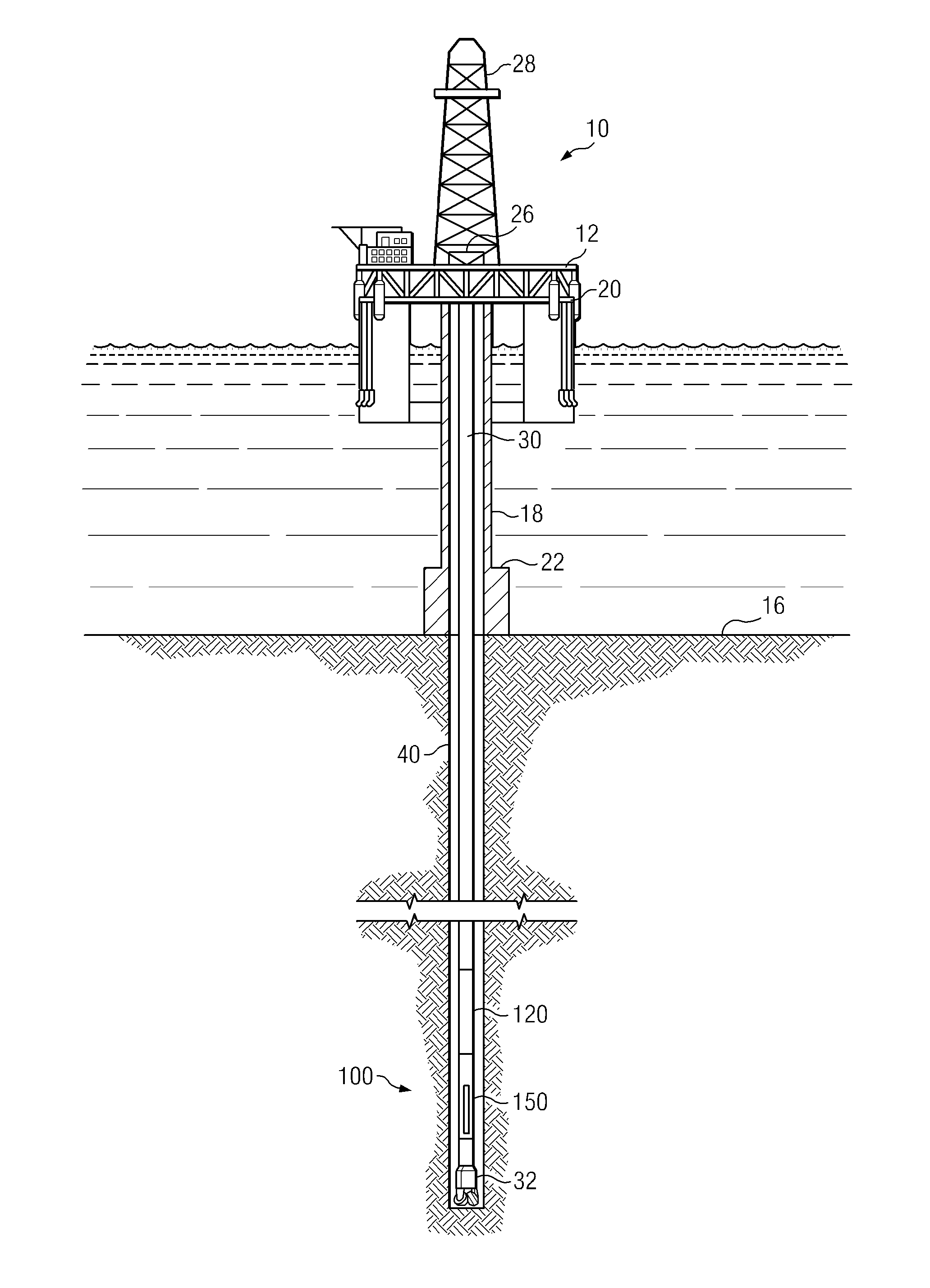
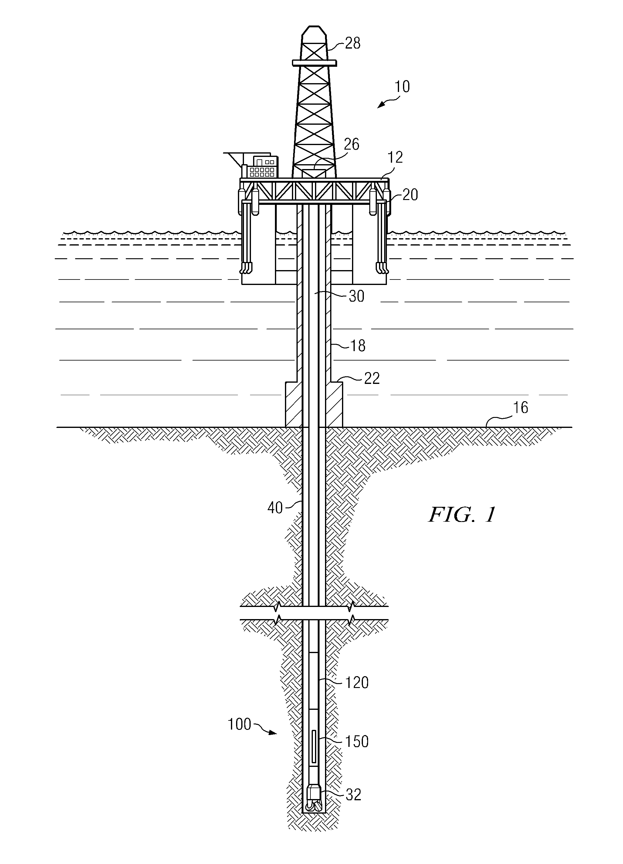
[0022]FIG. 2 depicts a flow chart of one exemplary method embodiment 200 in accordance with the present invention. As depicted, method 200 is a closed-loop method for geosteering. By closed-loop it is meant that the geosteering calculations and subsequent adjustments to the steering direction are made automatically downhole without the need for any uphole (surface) processing or decision making. Such autonomous downhole decision making is based on feedback obtained from various LWD measurements. A portion of the LWD data may optionally be transmitted uphole for surface monitoring of the closed loop geosteering process. At 202 of method 200 a subterranean borehole (or a section thereof) is drilled using convention directional drilling techniques (e.g., by rotating BHA 100 in the borehole). Logging while drilling measurements (preferably directional resistivity measurements) are acquired at 204. These LWD measurements are processed downhole while drilling to obtain a geosteering corre...

embodiment 250

[0026]FIG. 4 depicts a flow chart of another exemplary method embodiment 250 in accordance with the present invention. In the exemplary embodiment depicted first and second geometric 260 and geosteering 270 algorithms are utilized in parallel to achieve an optimum well placement. The geometric algorithm 260 is based upon a predetermined geometric well plan 262 derived, for example, from a field development plan. As is known to those of ordinary skill in the art, a typical field development plan is commonly designed to achieve maximum drainage and is often based upon structural knowledge of the field obtained from seismic profiles, offset wells, and previous wells drilled in the area. Conventional surveys are acquired at 264. These surveys typically include borehole azimuth and borehole inclination measurements and are commonly obtained at about 30 foot intervals in measured depth (e.g., when a new section of drill pipe is added to the drill string). A geometric well position is comp...


PUM


Abstract

A closed-loop method for geosteering includes acquiring logging while drilling data and processing the logging while drilling data downhole while drilling to obtain a geosteering correction (a correction to the drilling direction based upon the LWD measurements). The geosteering correction is further processed downhole to obtain new steering tool settings which are then applied to the steering tool to change the direction of drilling. These steps are typically repeated numerous times without the need for uphole processing or surface intervention.

Description

RELATED APPLICATIONS[0001]None.FIELD OF THE INVENTION[0002]The present invention relates generally to methods for drilling a subterranean borehole. More particularly, the invention relates to a downhole closed-loop method for geosteering.BACKGROUND OF THE INVENTION[0003]The use of on-site and remote geosteering methods are well known in the downhole drilling arts. During such geosteering operations, drilling typically proceeds according to a predetermined well plan (e.g., derived using geometric considerations in combination with a three dimensional model of the subterranean formations). Real-time geological measurements, for example, measurement while drilling (MWD), logging while drilling (LWD), and / or mud logging measurements, are made while drilling. Data obtained from these measurements are then used to make “on the fly” adjustments to the direction of drilling, for example, to maintain the drill bit at a desired location in a payzone.[0004]In prior art geosteering operations, ...

Claims


Application Information

Patent Timeline
Patent Type & Authority Applications(United States)
IPC IPC(8): G01V1/40
CPCE21B7/04E21B47/124E21B47/022E21B7/10E21B47/26E21B47/02E21B47/12
Inventor TCHAKAROV, BORISLAV J.WANG, TSILIGUENTHER, RODNEY S.CAO, THANH H.TANG, CAIMU
Owner SCHLUMBERGER TECH CORP
Why Eureka
Try Eureka