
Liquid crystal display device

a liquid crystal display and display device technology, applied in the field of liquid crystal display devices, can solve the problem of reducing the bezel width to a predetermined distance or less, and achieve the effect of reducing the bezel width and reducing light loss

Inactive Publication Date: 2012-03-01
SAMSUNG ELECTRONICS CO LTD
View PDF6 Cites 24 Cited by
  • Summary
  • Abstract
  • Description
  • Claims
  • Application Information

AI Technical Summary

Benefits of technology

[0013]One or more exemplary embodiments provide a liquid crystal display device to reduce a bezel width and improve optical efficiency.
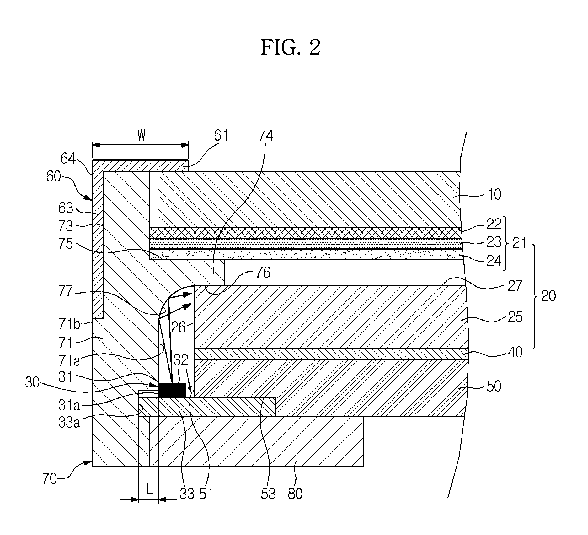
[0026]In another exemplary embodiment, a liquid crystal display device includes: a liquid crystal display panel; a light-guide portion arranged under the liquid crystal display panel; a light-emitting diode mounted on a printed circuit board such that a light-emitting surface of the light-emitting diode directs upward, the light-emitting diode adjacent to a side of the light-guide portion; and a side frame provided with a reflective surface to reflect light emitted upward from the light-emitting surface at a predetermined position and allow the reflected light to be incident to a side of the light-guide portion, wherein one side of the light-emitting diode is in contact with the side frame.
[0037]As is apparent from the aforementioned description, the liquid crystal display device of the exemplary embodiments described herein reduce the bezel width, and at the same time reduce light loss.

Problems solved by technology

For this reason, there is a limitation in reducing the bezel width to a predetermined distance or less.

Method used


Image

  • Liquid crystal display device
  • Liquid crystal display device
  • Liquid crystal display device

Examples


Embodiment Construction

[0042]Reference will now be made in detail to the exemplary embodiments, examples of which are illustrated in the accompanying drawings, wherein like reference numerals refer to the like elements throughout.

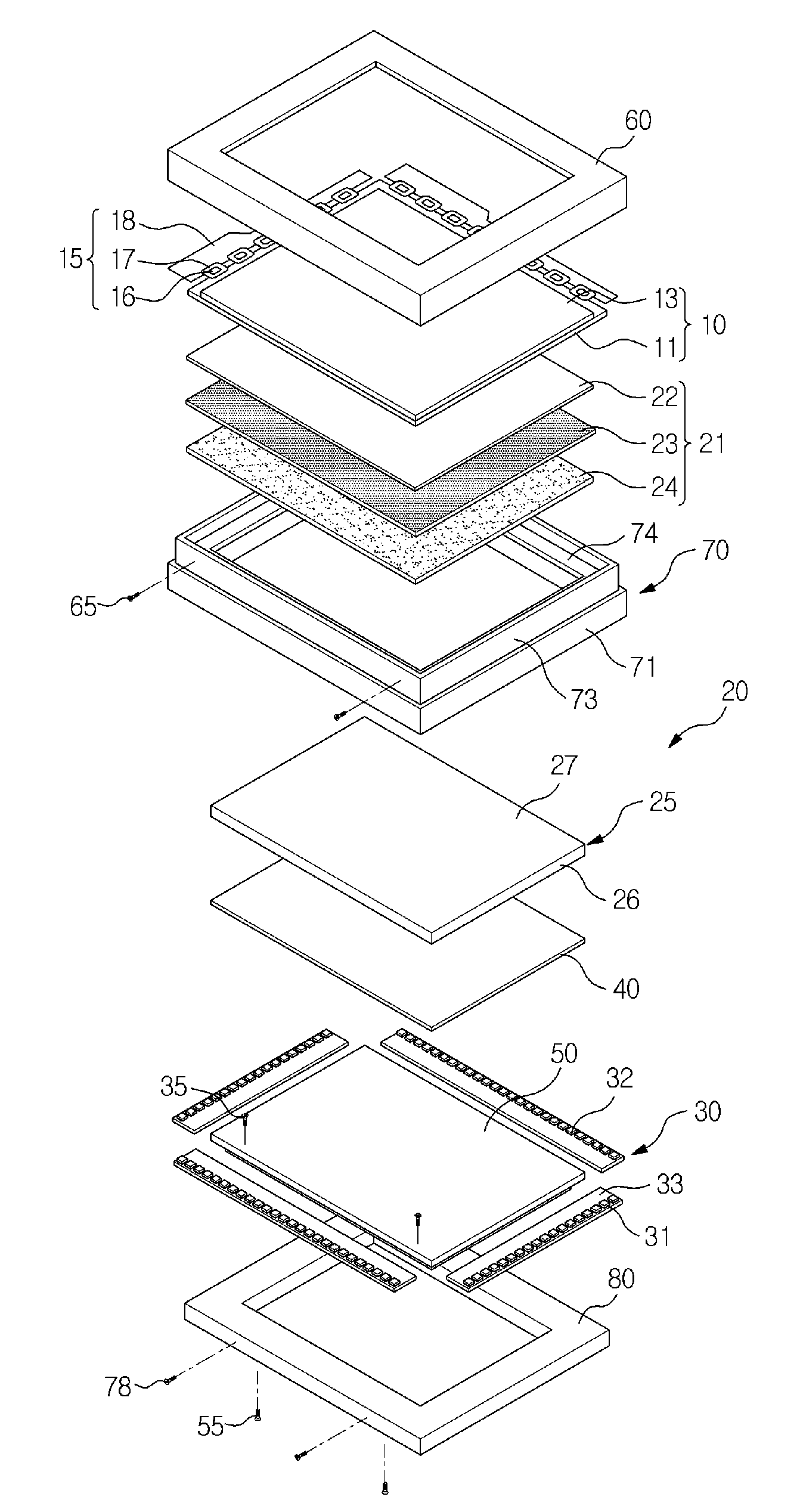
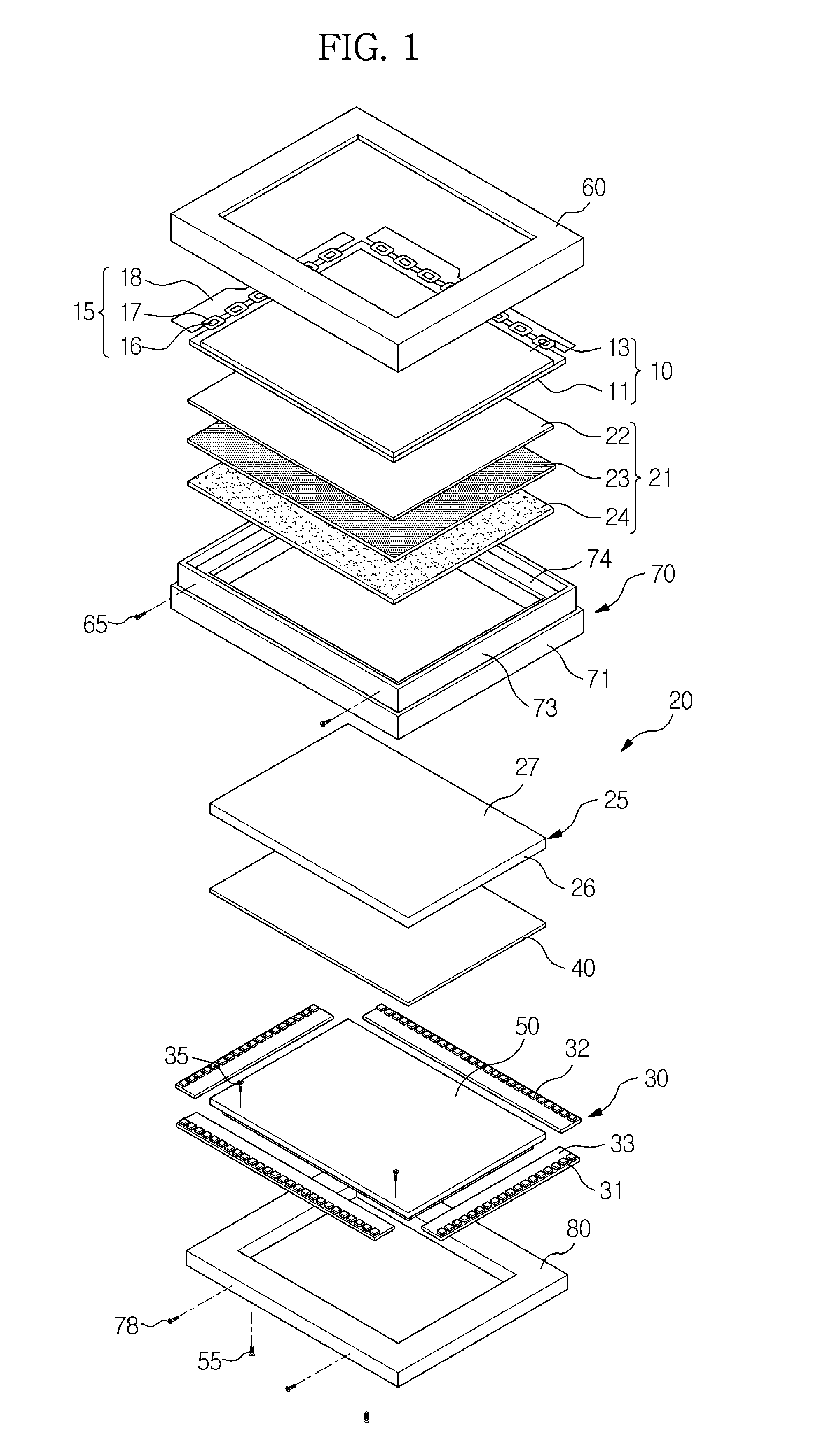
[0043]FIG. 1 is a perspective view illustrating a schematic structure of a liquid crystal display device according to one exemplary embodiment.

[0044]Referring to FIG. 1, the liquid crystal display device includes: a liquid crystal display panel 10; a backlight unit 20 arranged at the back of the liquid crystal display panel 10; a side frame 70 to support the liquid crystal display panel 10 and the backlight unit 20 such that the liquid crystal display panel 10 is spaced away from the backlight unit 20; and a top chassis 60 and a bottom chassis 50 arranged on the liquid crystal display panel 10 and under the backlight unit 20, respectively.

[0045]The liquid crystal display panel 10 further includes: a thin film transistor substrate 11 provided with a thin film transistor; a color f...


PUM


Abstract

A liquid crystal display device is provided. The liquid crystal display device includes at least one light-emitting surface mounted in a printed circuit board such that the light-emitting surface directs upward, and a side frame provided with a reflective surface to refract light from the light-emitting surface at a predetermined position and thus allow the light to be incident at a side of a light-guide portion. The light-emitting diode is arranged such that one side thereof contacts an inner surface of the side frame, thus minimizing a width of a bezel portion and preventing light loss.

Description

CROSS-REFERENCE TO RELATED APPLICATION(S)[0001]This application claims priority from Korean Patent Application No. 2010-0082327, filed on Aug. 25, 2010 in the Korean Intellectual Property Office, the disclosure of which is incorporated herein by reference in its entirety.BACKGROUND[0002]1. Field[0003]Apparatuses consistent with embodiments relate generally to a liquid crystal display device to reduce a bezel width and improve optical efficiency.[0004]2. Description of the Related Art[0005]A liquid crystal display (LCD) device displays an image using electrical and optical properties of liquid crystal. The liquid crystal display (LCD) device has advantages of small thickness, light-weight, low power consumption and low driving voltage and is thus widely utilized in the overall industry.[0006]The liquid crystal display includes a liquid crystal display panel in which the orientation of liquid crystal molecules and thus light transmittance are changed by applying an electric voltage to...

Claims


Application Information

Patent Timeline
IPC IPC(8): G02F1/13357G02F1/1333
CPCG02F1/133308G02F1/133605G02B6/0091G02B6/0085G02B6/0031
Inventor JEONG, KYUNG OCKJUNG, IL YONGYOO, JUN MO
Owner SAMSUNG ELECTRONICS CO LTD
Learn More