Objective

a technology of objective and mold, applied in the field of objective, can solve the problems of increasing mold production costs, unsuitability for large volumes, and inability to meet the requirements of large-scale production, and achieve the effect of low production price of mould for the objectives, and low number of optical functional areas

Inactive Publication Date: 2012-03-01
FRAUNHOFER GESELLSCHAFT ZUR FOERDERUNG DER ANGEWANDTEN FORSCHUNG EV
View PDF1 Cites 43 Cited by
  • Summary
  • Abstract
  • Description
  • Claims
  • Application Information

AI Technical Summary

Benefits of technology

[0004]Depending on requirements, several lenses and lens groups having different optical characteristics are necessitated in conventional objectives, for example to sufficiently correct geometric imaging errors or color errors. For lowering production costs, glass lenses can be produced, besides conventional grinding and polishing methods, for example in blank molding technology. Still, cost-intensive mechanical lens mounts and an assembly with different processing steps are necessitated.
[0021]Since the number of optical functional areas is relatively low according to embodiments, the production price of the mould for the objectives according to these embodiments is also low. According to embodiments, not only the number of optical functional areas is low, but the optical functional areas can also be described with spherical, conical or biconical areas, so that a robust and inexpensive production of the mould can be obtained, for example for plastic forming, as only a few, for example spherical, conical or biconical areas are used, which can be described in a simple mathematical manner. Additionally, due to the reduced number of functional areas, the negative influence of absorption losses at every optical functional area on the light intensity of the objective is reduced. Since there is no intermediate imaging, the optical path can be shortened and, hence, a more compact design can be obtained. According to embodiments, the system aperture is located in the optical path between the optical functional elements, so that it is possible to correct possibly existing image errors with less functional areas, and hence to obtain higher image quality. Additionally, according to embodiments, a refractive functional area of the monolithic objective serving as exit area is implemented in a planar manner, so that an image sensor that can be encapsulated with a planar cover glass can be directly attached to or mounted on this functional area without any additional mechanical components, which significantly lowers assembly tolerances and reduces costs.

Problems solved by technology

Still, cost-intensive mechanical lens mounts and an assembly with different processing steps are necessitated.
Depending on the design, these objectives are very sensitive to production and assembly tolerances, such that the same are unsuitable for large volumes.
Despite the ultra-precision processing technologies common nowadays, mold production costs increase with every optical functional area and its mold complexity.
This increases production costs and additionally reduces the light intensity of the objective due to absorption losses.
Additionally, the mathematical description the optical functional area is complex, which makes production of the same more difficult and more cost-intensive.
However, with a system aperture arranged outside the objective it is very difficult to correct imaging errors due to the lack of symmetry within the system.
Further, the embodiments of the above-stated patent literature show an arrangement of the image sensor with an air gap to the last, mostly bent optical functional area, so that additional and cost-intensive mechanical components are necessitated for alignment and permanent fixing of the image sensor.
This increases the difficulty of mounting the sensor exactly and with few tolerances.
Since the objective consists of a monolithic body, additional mechanical mount parts can be omitted, as it is otherwise not possible in reflective and refractive objectives having a modular structure.
Since the number of optical functional areas is relatively low according to embodiments, the production price of the mould for the objectives according to these embodiments is also low.

Method used


Image

  • Objective
  • Objective
  • Objective

Examples


Embodiment Construction

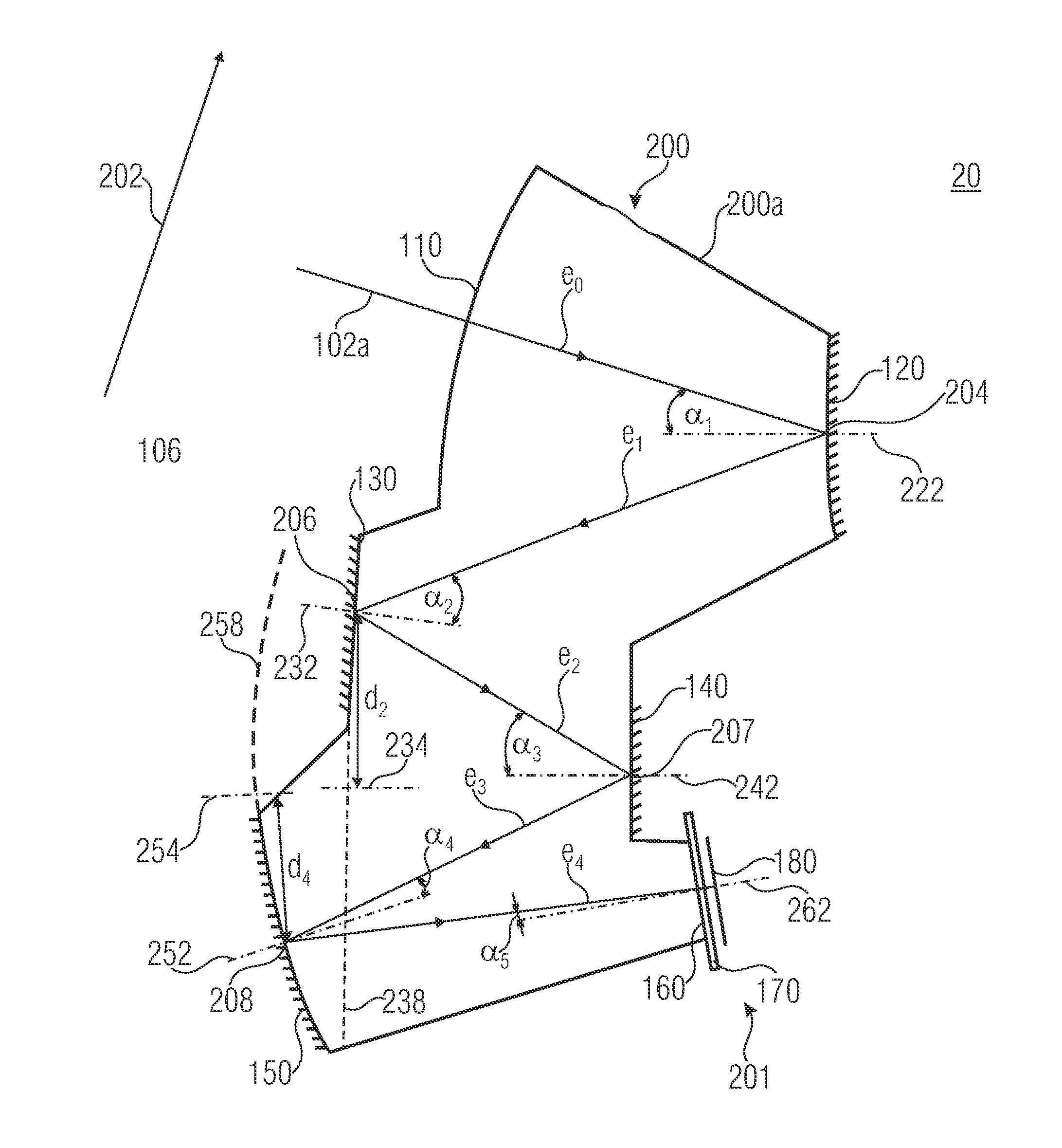
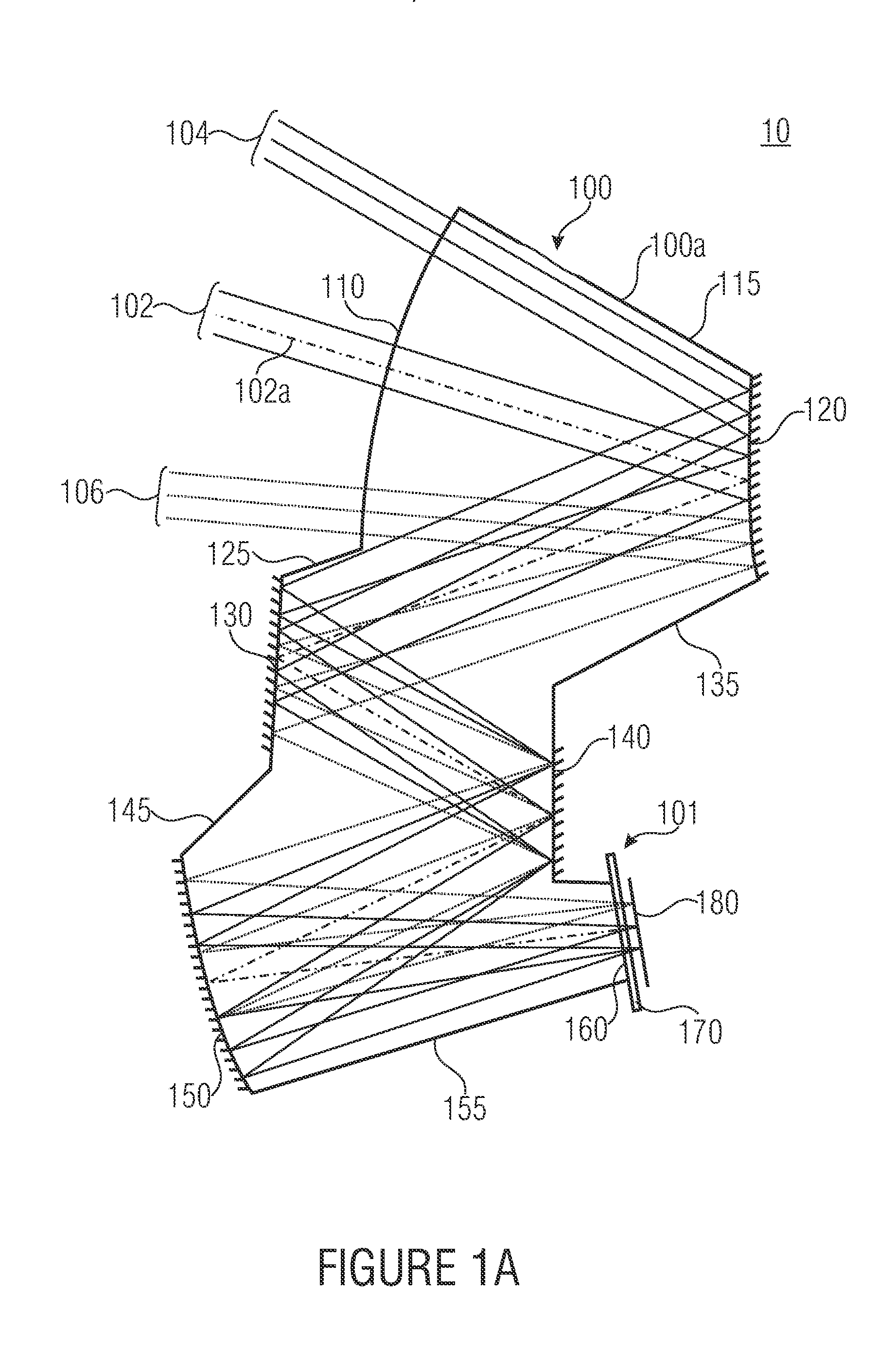
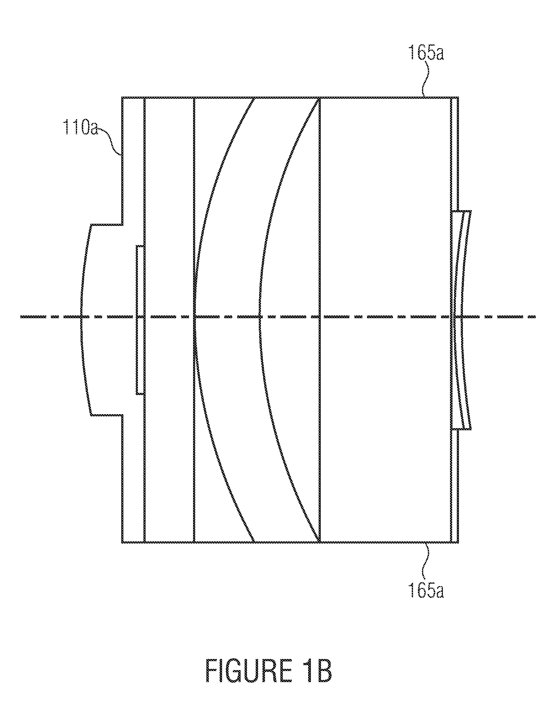
[0026]FIGS. 1a-c show an image-capturing system having an objective 100 according to an embodiment and an image sensor 101.

[0027]The objective 100 is, in particular, a center shading-free monolithic objective having refractive and reflective functional areas. It consists of a monolithic body 100a made of a material at least partly transparent for part of an electromagnetic spectrum, the surface of which comprises portions defining specific functional areas 110, 120, 130, 140, 150 and 160, wherein the functional areas 110 and 160 are refractive functional areas serving as entrance area and exit area, respectively, and the optical functional areas 120, 130, 140, 150 are reflective functional areas serving as respective mirrors. The functional areas 110-160 are implemented such that a center shading-free, folded optical path is formed from the entrance area 110 through the monolithic body 100a via mirrors 120-150 to the exit area 160 in the order just stated, which is indicated in FIG....


PUM


Abstract

An objective is described consisting of a monolithic body of a material at least partly transparent for a part of an electromagnetic spectrum, and whose surfaces include a first optical refractive functional area serving as entrance area through which electromagnetic radiation can enter the objective, a second optical reflective functional area serving as a first mirror, a third optical reflective functional area serving as a second mirror, a fourth optical reflective functional area serving as a third mirror, a fifth optical reflective functional area serving as a fourth mirror, and a sixth optical refractive functional area serving as an exit area through which electromagnetic radiation can exit the objective, wherein the first to sixth optical functional areas are implemented such that a center shading-free, folded optical path extends from the entrance area through the monolithic body via first to fourth mirrors to the exit area, wherein no intermediate image level is located in the same between the entrance area and the exit area.

Description

CROSS-REFERENCE TO RELATED APPLICATIONS[0001]This application claims priority from German Patent Application No. 102010040030.0, which was filed on Aug. 31, 2010, and is incorporated herein in its entirety by reference.BACKGROUND OF THE INVENTION[0002]The present invention relates to objectives.[0003]Many products necessitate compact and light objectives having a high imaging performance, which should, however, be cost-effective to produce.[0004]Depending on requirements, several lenses and lens groups having different optical characteristics are necessitated in conventional objectives, for example to sufficiently correct geometric imaging errors or color errors. For lowering production costs, glass lenses can be produced, besides conventional grinding and polishing methods, for example in blank molding technology. Still, cost-intensive mechanical lens mounts and an assembly with different processing steps are necessitated.[0005]Further, lenses can be produced cheaply in high quanti...

Claims


Application Information

Patent Timeline
Patent Type & Authority Applications(United States)
IPC IPC(8): G02B17/08
CPCG02B17/0844
Inventor SEIDL, KRISTOFKNOBBE, JENS
Owner FRAUNHOFER GESELLSCHAFT ZUR FOERDERUNG DER ANGEWANDTEN FORSCHUNG EV
Why Eureka
Try Eureka