Cooling System for Onboard Electrical Power Converter, and Electrical Power Converter for Railway Vehicle

Inactive Publication Date: 2012-03-01
HITACHI LTD
View PDF11 Cites 29 Cited by
  • Summary
  • Abstract
  • Description
  • Claims
  • Application Information

AI Technical Summary

Benefits of technology

[0016]With such a cooling system according to the present invention that cools an electrical power conver

Problems solved by technology

As a result, it has been difficult to provide a structure in which this system can conveniently be housed within the front machinery compartment of an electric automobile.
Moreover because, while the direction of flow of the air entering into the heat exchanger is approximately perpendicular to the upper surface of the evaporation chamber, by contrast, the a

Method used


Image

  • Cooling System for Onboard Electrical Power Converter, and Electrical Power Converter for Railway Vehicle
  • Cooling System for Onboard Electrical Power Converter, and Electrical Power Converter for Railway Vehicle
  • Cooling System for Onboard Electrical Power Converter, and Electrical Power Converter for Railway Vehicle

Examples


embodiment # 1

Embodiment #1

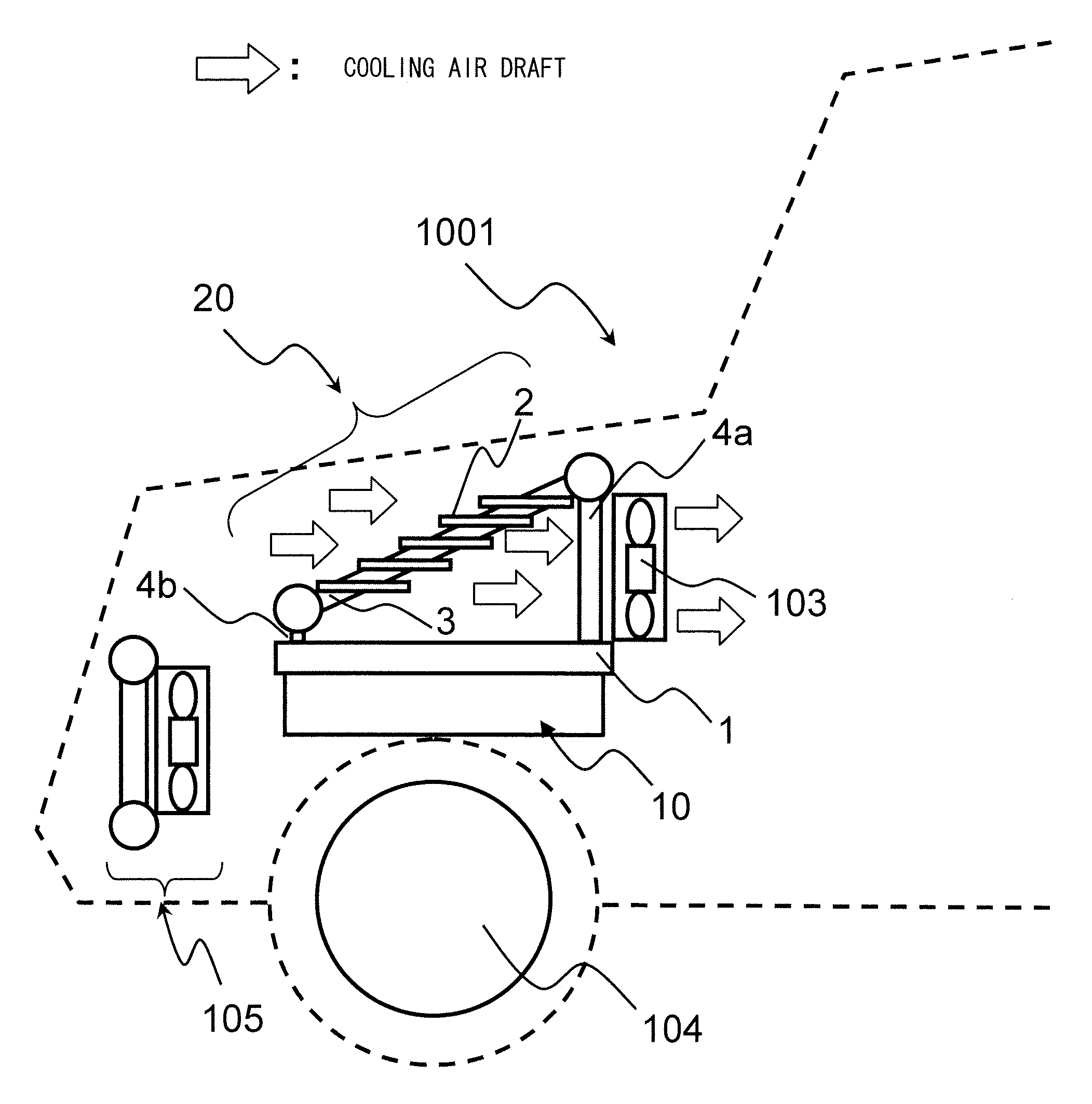
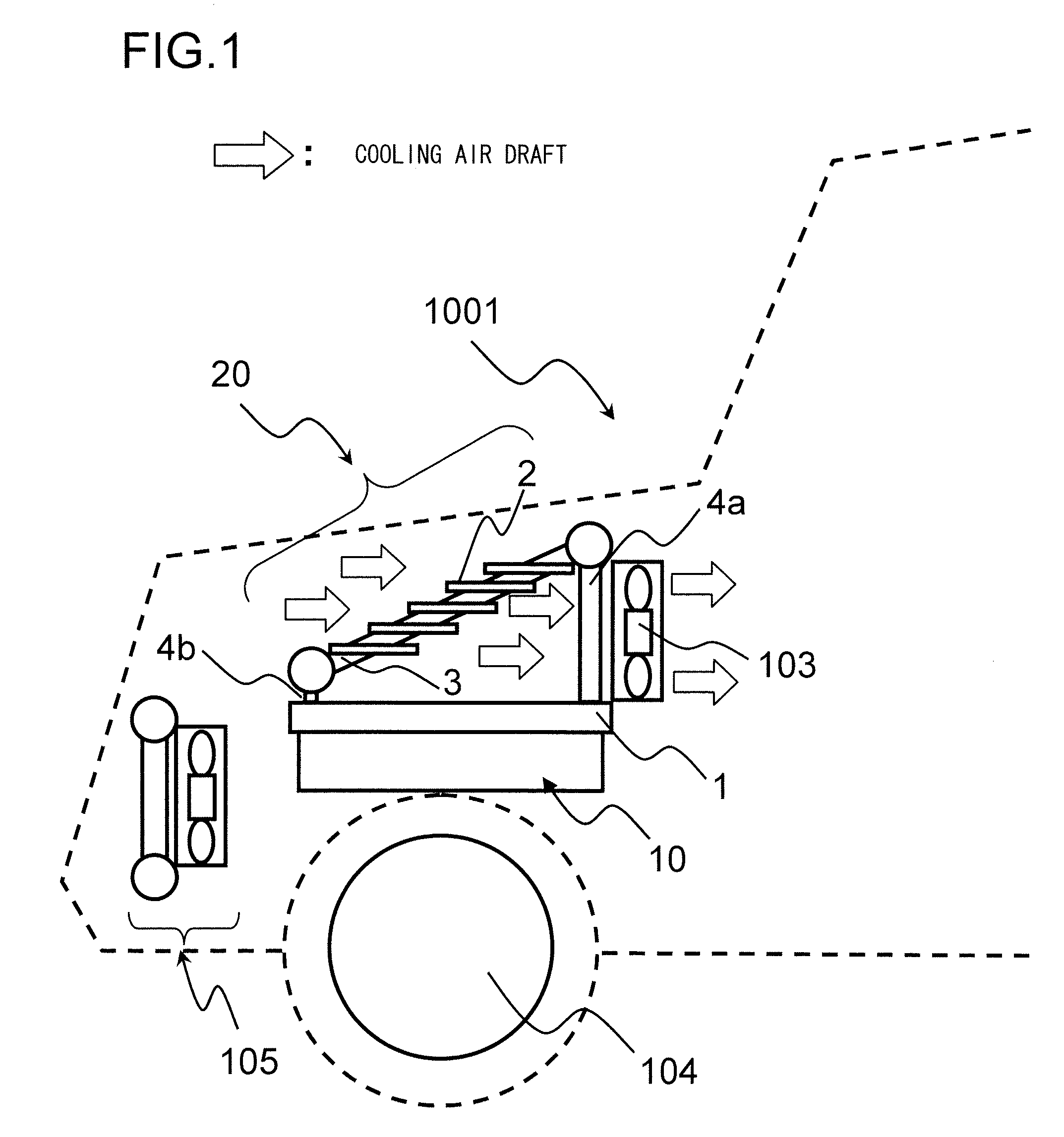
[0028]FIG. 1 is a figure showing a first embodiment of the cooling system for an onboard power converter according to the present invention, and shows a case in which this cooling system is applied to an electric automobile. This figure shows the front part of a front machinery compartment portion of an electric automobile that includes an electrical power converter to which the cooling system of this embodiment is provided, as seen from the side. An electrical power converter 10 for driving a motor 104 that propels this electric automobile 1001 is provided in the interior of this front machinery compartment. As will be described hereinafter, electronic components that make up an inverter circuit and so on are provided in this electrical power converter 10. A cooling system 20 is provided to the electrical power converter 10 for cooling the electrical power converter 10. And an air blower 103 for supplying a draft of cooling air to the cooling system 20 is provided to t...

embodiment # 2

Embodiment #2

[0048]While a cooling system 20 of the evaporative cooling type was explained in the first embodiment described above, the present invention can also be applied even if the evaporative cooling method is not employed. With the cooling system 120 shown in FIG. 7, a method is employed in which a liquid coolant (for example cooling water) is forcibly circulated by a circulation pump 7 and does not change its physical phase. It should be understood that, to structural elements that are the same as ones shown in FIG. 3, the same reference symbols are appended. Heat exchange between the electrical power converter 10 and the coolant is performed by a coolant tank 121. A heat exchanger 21 is provided above the coolant tank 121, with a plurality of heat transfer conduits 3 connecting between a coolant head 5c that is located at the downstream of a flow of cooling air and a coolant head 5d that is provided at the upstream thereof. The coolant heat 5c is connected by a coolant cond...

embodiment # 3

Embodiment #3

[0051]FIG. 8 is a figure showing a third embodiment of the cooling system of the present invention, in which the present invention is applied to cooling an electrical power converter that is mounted to a railway vehicle. In order to enlarge the space in the passenger cabin of a railway vehicle so as to increase the number of passengers who can ride therein, the electrical power converter that drives an electrical railway vehicle (hereinafter termed an “electric train carriage”) is often installed underneath the floor of the passenger cabin. Due to this, the dimension in the height direction of the space in which this electrical power converter can be mounted is limited.

[0052]FIG. 8 is a schematic cross sectional figure of an electric train carriage as seen from its direction of travel. A casing 400 in which an electrical power converter is housed is fitted under the floor of the body 1003 of this electric train carriage. An inlet aperture 401 is provided at one side of ...


PUM


Abstract

A cooling system for an onboard electrical power converter in which a heat dissipation surface extends parallel to a flow of cooling air draft includes: a coolant tank containing coolant that includes a bottom surface being in thermal contact with the heat dissipation surface; a first conduit provided connecting to an upper surface of the coolant tank, the coolant flowing into the first conduit; a heat exchanger that comprises second conduits arranged with opposing the upper surface, and conducts the coolant to upstream; and a return unit that returns the coolant to the coolant tank; wherein the heat exchanger comprises heat dissipation fins through which the cooling air draft passes from a first to a second side, the heat dissipation fins being provided on surfaces of the second conduits, the first side not facing the coolant tank and the second side facing the coolant tank.

Description

INCORPORATION BY REFERENCE[0001]The disclosure of the following priority application is herein incorporated by reference:[0002]Japanese Patent Application No. 2010-194030, filed Aug. 31, 2010.BACKGROUND OF THE INVENTION[0003]1. Field of the Invention[0004]The present invention relates to a cooling system for an onboard electrical power converter that is mounted to an electric automobile, a hybrid automobile, or a railway vehicle or the like, and to an electrical power converter for a railway vehicle.[0005]2. Description of Related Art[0006]With an electric automobile, a hybrid automobile, or a railway vehicle, a motor is provided in order to serve as a source of motive power, and an electrical power converter such as an inverter or the like is provided in order to control the electrical power supplied to this motor. Such an electrical power converter typically includes a power module that includes power semiconductors such as IGBTs (Insulated Gate Bipolar Transistor) or the like, a ...

Claims


Application Information

Patent Timeline
IPC IPC(8): H05K7/20F28D15/00
CPCH05K7/20936F28D15/0266H05K7/20927B61C5/02F28F1/34Y02T30/10H01L2924/0002H01L23/427B61C17/04H01L2924/00F28F13/06F28D15/0233Y02T30/00
Inventor SUZUKI, OSAMUYASUDA, YOSUKEHORIUCHI, KEISUKEHAYASHI, TOMOONISHIHARA, ATSUOFUNAKOSHI, SUNAO
Owner HITACHI LTD
Why Eureka
Try Eureka