Apparatus and method for controlling a tunable matching network in a wireless network

a wireless network and wireless technology, applied in the field of electrical circuit impedance matching, can solve the problems of inability less than desirable signal-to-noise ratio (snr) in both uplink and downlink cellular transmissions, and the inability of passive matching networks to provide antenna or power amplifier matching across multiple frequency bands

Inactive Publication Date: 2012-03-01
SAMSUNG ELECTRONICS CO LTD
View PDF14 Cites 126 Cited by
  • Summary
  • Abstract
  • Description
  • Claims
  • Application Information

AI Technical Summary

Benefits of technology

[0010]In yet another exemplary embodiment, a mobile station in a wireless network is provided. The mobile station includes an antenna, a front end module and a power amplifier. A first tunable matching network (TMN) is operably connected to the front end module and the antenna. The first TMN includes a first plurality of immittance elements. A first voltage standing wave ratio (VSWR) detector is configured to detect an antenna ratio of a signal from the front end module and a signal reflected from the first TMN. A second TMN is operably connected to the front end module and the power amplifier. The second TMN includes a second plurality of immittance elements. A second VSWR detector configured to detect a power amplifier ratio of a signal from the power amplifier and

Problems solved by technology

The large frequency variation of antenna impedance prevents effective signal power transfer across all bands and results in less than desirable signal-to-noise ratio (SNR) in both the uplink and downlink cellular transmissions.
Radio frequency (RF) amplifiers for wireless equipment also suffer problems with impedance matching.
A common issue in implementation of a multi-band or multi-mode power amplifier is in achieving optimum performance from the transmitter

Method used


Image

  • Apparatus and method for controlling a tunable matching network in a wireless network
  • Apparatus and method for controlling a tunable matching network in a wireless network
  • Apparatus and method for controlling a tunable matching network in a wireless network

Examples


Embodiment Construction

[0022]FIGS. 1 through 9, discussed below, and the various embodiments used to describe the principles of the present disclosure in this patent document are by way of illustration only and should not be construed in any way to limit the scope of the disclosure. Those skilled in the art will understand that the principles of the present disclosure may be implemented in any suitably arranged wireless network.

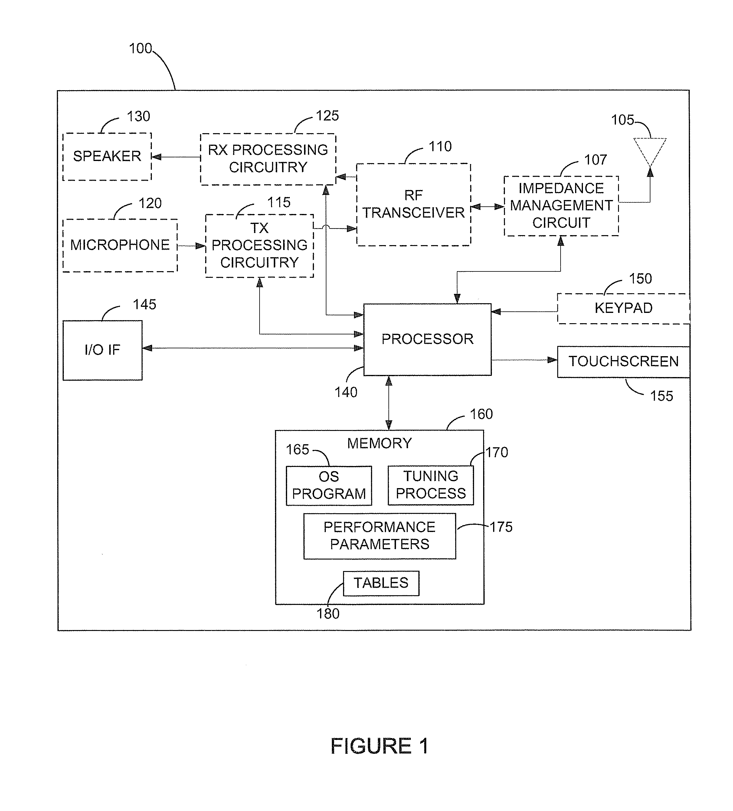
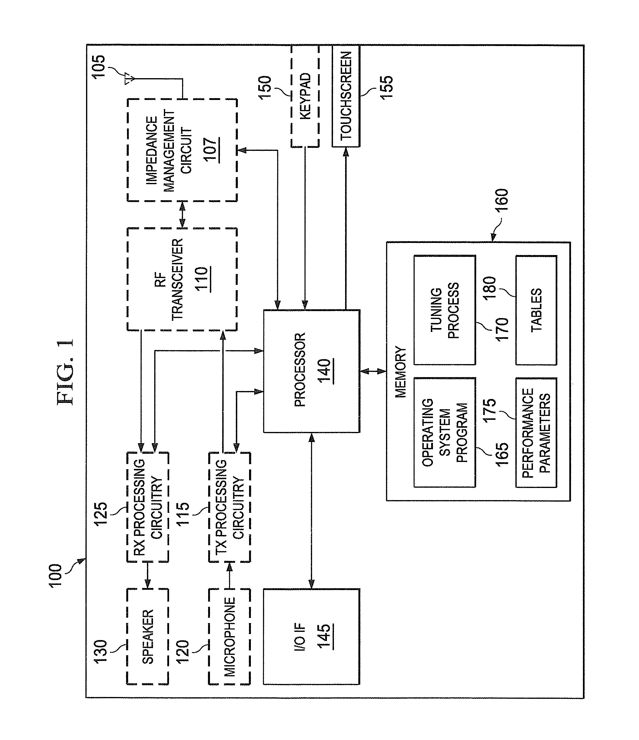
[0023]FIG. 1 illustrates a wireless mobile station according to the present disclosure. Mobile station 100 comprises antenna 105, impedance management circuit, 107, frequency (RF) transceiver 110, transmit (TX) processing circuitry 115, microphone 120, and receive (RX) processing circuitry 125. Mobile station 100 also comprises speaker 130, processor 140, input / output (I / O) interface (IF) 145, keypad 150, touchscreen 155, and memory 160. Memory 160 further comprises basic operating system process 165, matching process 170, performance parameters 175, and tables 180. In these exampl...


PUM


Abstract

An apparatus and method manage impedance values in a radio in a wireless network. The apparatus includes a tunable matching network (TMN) positioned on a path between a transceiver and an antenna. The TMN includes a plurality of immittance elements. A voltage standing wave ratio (VSWR) detector is configured to detect a ratio of a signal passing the VSWR detector and a signal reflected from the TMN. A control circuit is configured to identify an operating setting for the radio, set a number of the immittance elements based on the operating setting, monitor the ratio detected by the VSWR detector, and modify a setting of at least one of the immittance elements based on the ratio detected.

Description

CROSS-REFERENCE TO RELATED APPLICATION(S) AND CLAIM OF PRIORITY[0001]The present application is related to U.S. Provisional Patent Application No. 61 / 379,218, filed Sep. 1, 2010, entitled “HYBRID CONTOL OF TUNABLE ANTENNA MATCHING” and U.S. Provisional Patent Application No. 61 / 493,828, filed Jun. 6, 2011, entitled “HYBRID CONTROL OF TUNABLE IMPEDANCE MATCHING”. Provisional Patent Application Nos. 61 / 379,218 and 61 / 493,828 are assigned to the assignee of the present application and is hereby incorporated by reference into the present application as if fully set forth herein. The present application hereby claims priority under 35 U.S.C. §119(e) to U.S. Provisional Patent Application Nos. 61 / 379,218 and 61 / 493,828.TECHNICAL FIELD OF THE INVENTION[0002]The present application relates generally to impedance matching in electrical circuits and, more specifically, to controlling a tunable matching network.BACKGROUND OF THE INVENTION[0003]Efficient transfer of signal power to or from an a...

Claims


Application Information

Patent Timeline
IPC IPC(8): H03H7/38H04B1/38
CPCH03H7/38H03H7/40H04B1/0458
Inventor BROBSTON, MICHAEL L.ZHU, XUBUI, AU DUYHUTCHESON, GEORGE Z.
Owner SAMSUNG ELECTRONICS CO LTD
Why Eureka
Try Eureka