Method for manufacturing optical film laminate including polarizing film

a manufacturing method and technology of optical film, applied in the direction of polarizing elements, instruments, applications, etc., can solve the problems of resin actually becoming unstretchable, not easy to solve, and not as yet possible to obtain polarizing films, so as to improve the stretching ratio, and improve the molecular orientation of pva

Active Publication Date: 2012-03-08
NITTO DENKO CORP
View PDF3 Cites 66 Cited by
  • Summary
  • Abstract
  • Description
  • Claims
  • Application Information

AI Technical Summary

Benefits of technology

[0052]With the solid line in FIG. 23, it has been confirmed that the molecular orientation of the PVA is improved with increase of the stretching temperature in the elevated temperature in-air stretching of the PVA type resin layer included in the stretched laminate. In addition, with the broken line in FIG. 23, it has been confirmed that the molecular orientation of the PVA is improved with increase of the stretching ratio under the elevated temperature in-air stretching of the PVA type resin layer included in the stretched laminate. Improving the molecular orientation or enhancing the extent of crystallization of the PVA before the second stage in-boric acid solution stretching is effective to improve the resulting molecular orientation of the PVA after the in-boric acid solution stretching. Further, it can be noticed in the T-P diagrams for the later described examples that, as the result of the improvement of the molecular orientation of the PVA, it is also possible to imp

Problems solved by technology
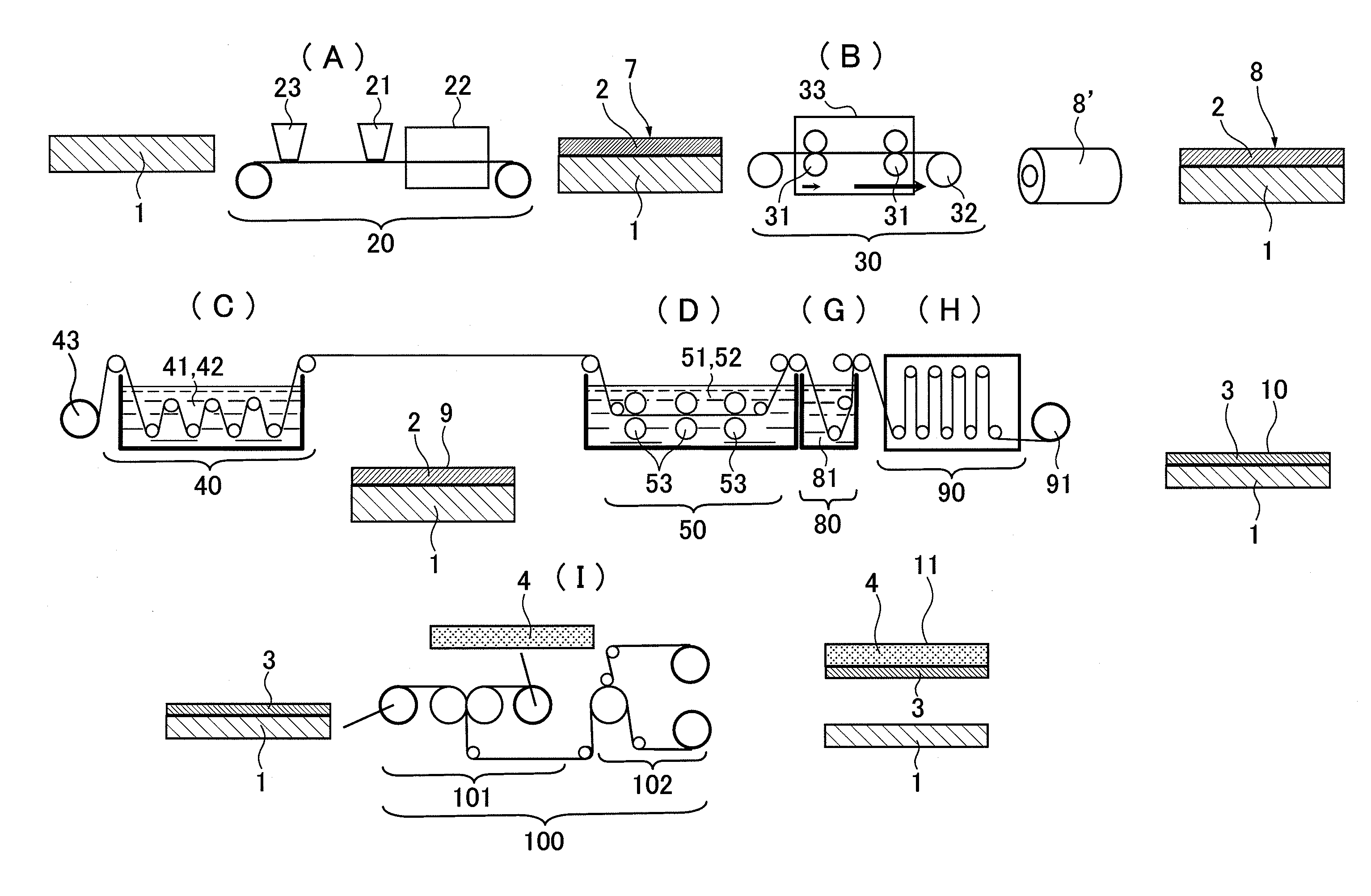
It should however be noted that in these methods, it has not as yet been possible to obtain polarizing films meeting requirements for optical properties of contrast ratio of 1000:1 or more and maximum luminance of 500 cd/m2 or more which are required for display

Method used


Image

  • Method for manufacturing optical film laminate including polarizing film
  • Method for manufacturing optical film laminate including polarizing film
  • Method for manufacturing optical film laminate including polarizing film

Examples


example 1

[0206]A continuous web of substrate has been produced from a non-crystallizable ester type thermoplastic resin comprising isophthalic acid-copolymerized polyethylene terephthalate (hereinafter referred as “non-crystallizable PET”) containing 6 mol % of isophthalic acid copolymerized therein. The glass transition temperature of the non-crystallizable PET is 75° C. A laminate comprising a continuous web of non-crystallizable PET substrate and polyvinyl alcohol (hereinafter referred as “PVA”) layer has been produced in accordance with the following procedures. It should be noted that the glass transition temperature of PVA is 80° C.

[0207]First, a non-crystallizable PET substrate 1 with a thickness of 200 μm has been prepared together with a PVA solution having a PVA concentration of 4 to 5 wt % which has been prepared by dissolving powders of PVA of a degree of polymerization of 1000 or higher and a degree of saponification of 99% or higher in water. Then, the PVA solution has been app...

example 2

[0216]In the example 2, as in the example 1, a laminate has at first provided by forming a 7 μm-thick PVA layer on a non-crystallizable PET substrate, then the laminate including the 7 μm-thick PVA layer has been subjected to a preliminary in-air stretching, to a stretching ratio of 1.8 to thereby form a stretched laminate, and thereafter the stretched laminate has been immersed in a dyeing solution containing iodine and potassium iodide at a solution temperature of 30° C. to form a dyed laminate including a PVA layer having iodine impregnated therein. In the example 2, in contrast to the example 1, a cross-linking process has additionally been carried out by immersing the dyed laminate for 60 seconds in the boric acid cross-linking solution at a solution temperature of 40° C. for the purpose of cross-linking PVA molecules in the PVA layer having iodine impregnated therein. The boric acid cross-linking solution in this process has contained 3 parts in weight of boric acid with respe...

example 3

[0220]In the example 3, as in the example 1, a laminate has first been prepared by forming a 7 μm-thick PVA layer on a non-crystallizable PET substrate, then the laminate including the 7 μm-thick PVA layer has been subjected to a preliminary in-air stretching to attain a stretching ratio of 1.8, to thereby form a stretched laminate. In the example 3, in contrast to the example 1, an insolubilizing process has been additionally incorporated, for insolubilizing the PVA layer in the stretched laminate and having PVA molecules oriented, the insolubilizing process being carried out by immersing the stretched laminate for 30 seconds in boric acid insolubilizing solution at a solution temperature of 30° C. The boric acid insolubilizing solution in this process has contained 3 parts in weight of boric acid with respect to 100 parts in weight of water. The technical effect obtained by the insolubilization process in the example 3 is that the PVA layer in the stretched laminate is insolubiliz...


PUM

PropertyMeasurementUnit
Temperatureaaaaaaaaaa

Abstract

A method for manufacturing an optical film laminate including subjecting a laminate including the non-crystallizable ester type thermoplastic resin substrate and the polyvinyl alcohol type resin layer formed on the non-crystallizable ester type thermoplastic resin substrate to an elevated temperature in-air stretching to form a stretched laminate comprising a stretched intermediate consisting of a molecularly oriented polyvinyl alcohol type resin, impregnating the dichroic material in the stretched laminate to form a dyed laminate including a dyed intermediate comprising a polyvinyl alcohol type resin layer having the dichroic material impregnated therein in an oriented state, and stretching the dyed laminate in boric acid solution to form an optical film laminate.

Description

TECHNICAL FIELD[0001]The present invention relates to a method for manufacturing an optical film laminate including a polarizing film. The polarizing film manufactured according to the present invention is a polarizing film comprising a polyvinyl alcohol type resin having a dichroic material impregnated therein in an oriented state and formed on a non-crystallizable ester type thermoplastic resin substrate.BACKGROUND ART[0002]A well-known method for manufacturing a polarizing film or a so-called polarizer (hereinafter, referred as “a polarizing film”) comprises steps of subjecting a film of polyvinyl alcohol resin type material (hereinafter, referred as “PVA type resin”) to dyeing and stretching processes to thereby provide a stretched film having a dichroic material impregnated therein with an oriented state. Among them, a polarizing film manufactured using a thermoplastic resin substrate and a method of manufacturing the same have been already known publicly as shown in the concep...

Claims


Application Information

Patent Timeline
IPC IPC(8): B32B37/14B32B37/12B05D3/10B32B38/00B05D3/12B05D5/06B32B37/02B29C55/04B29K29/00B29K67/00B29L9/00B29L11/00G02B5/30G02F1/1335
CPCB29C55/026Y10T428/2495B29K2067/00B29K2995/0034G02B1/105G02B5/3083G02F1/133528G02F2001/133638G02F2201/50G02F2202/22G02F2202/28G02B5/30B29C65/00B29D11/00H01L2924/30107B29K2029/04Y10T428/265G02B5/3033Y10T428/1041H01L2924/00G02B1/14C09K2323/031G02F1/133638G02B5/3025H05B33/02H10K50/84H10K50/85H10K50/868
Inventor GOTO, SHUSAKUKITAGAWA, TAKEHARUMIYATAKE, MINORUMORI, TOMOHIROKAMIJO, TAKASHI
Owner NITTO DENKO CORP
Why Eureka
Try Eureka